|
||

|
|
Engine Compartment Wiringregulators is covered in this article. The following topics are discussed in this article -
Engine Compartment WiringWhen a short in the wire to the backup lights burned out the ignition switch and shut him down, Dave decided that it would be prudent to rewire the whole engine compartment, since he found a number of other areas in which insulation had either worn off or burned off the wires. The "stock" wiring arrangement in the engine compartment (no CDI or CompuFire) is shown roughly in the following diagram. (See more on the "Stock" Coil/Distributor Wiring below.)
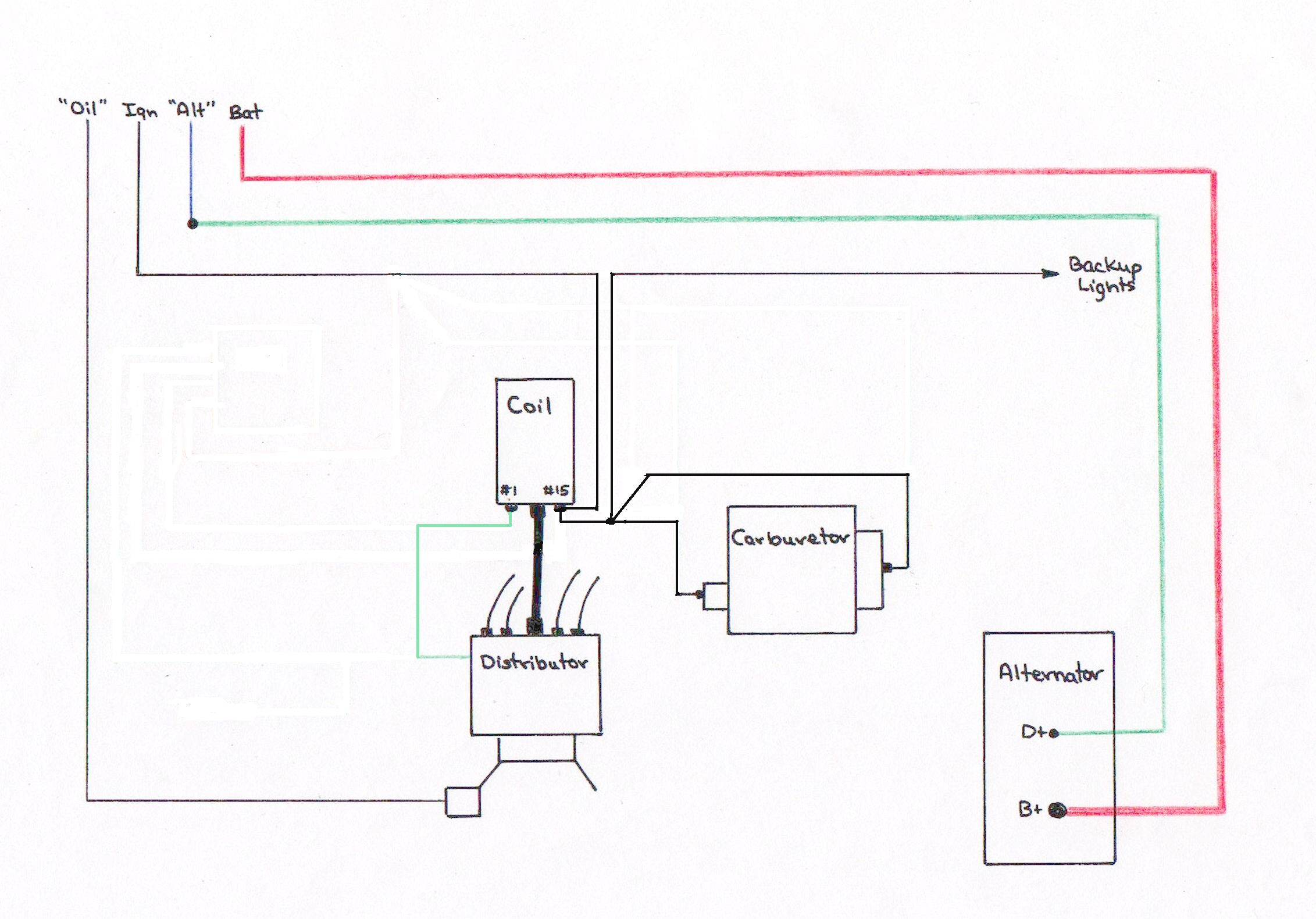 Rough Schematic of Engine WiringIn process of this engine re-wiring job, Dave installed what he calls a "power block" on the left fresh air nozzle to keep all of the wiring straight. Following is a very rough wiring diagram showing the wiring layout on the power block, followed by a photograph of the power block after the engine compartment re-wiring was complete.
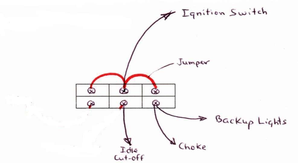 Power Block Wiring Layout
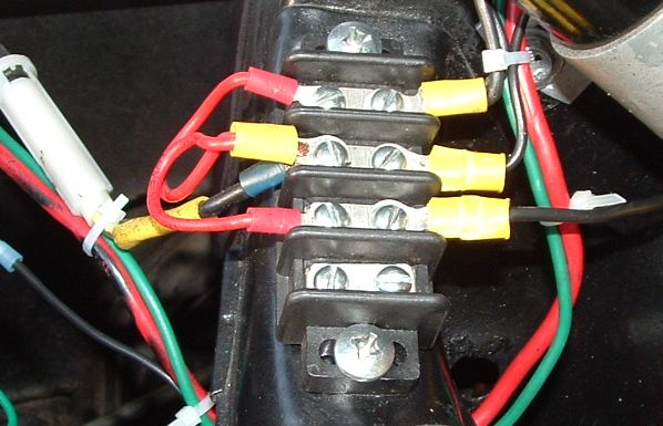 The Power Block
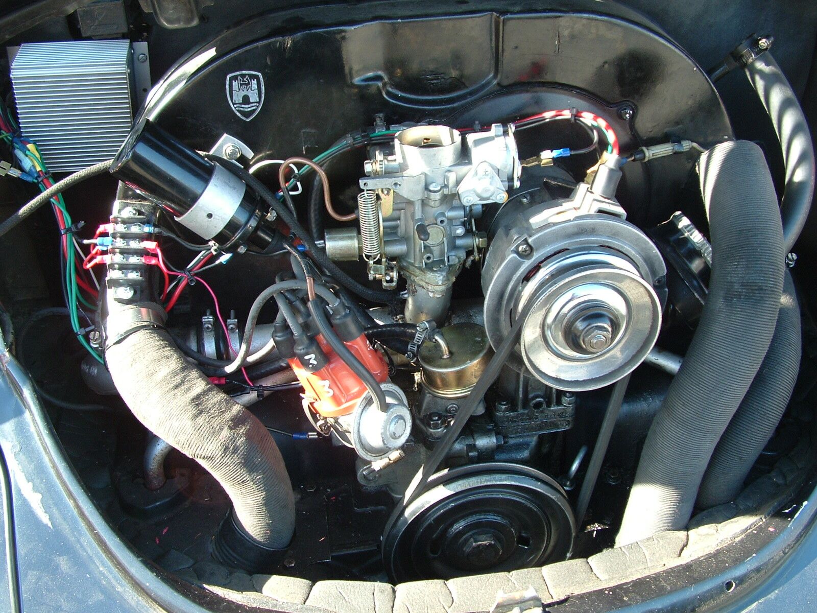 New Engine WiringNot long after completing his engine re-wiring, Dave accidentally pulled the wire to the automatic choke loose when the key was on (Dave had just completed timing the distributor); the wire, which was hot, of course, fell down and shorted against the alternator -- causing the ignition switch to burn out AGAIN! To prevent this from happening in the future, it was suggested to Dave that he put a 25-amp fuse in the wire that goes from the ignition switch back to the engine compartment, right near the switch at the plug. Such a fuse, the guy said, "will power everything, but blow if something screws up, which will kill power to the sensitive stuff. Better to replace a fuse that a switch." A good idea. Dave has now replaced his ignition switch again for the second time and has installed a 25-amp fuse in the wire from the ignition switch, just "upstream" of the power block he installed in his engine compartment. "Stock" Coil/Distributor Wiring
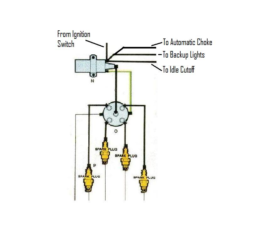 Coil/Distributor WiringThe black wire coming into the positive terminal on the coil (#15) is from fuse #12, which receives power from the ignition switch. Note three black wires leading from that terminal - one to the automatic choke, one to the backup lights, and one to the idle cut-off valve on the carburetor. The positive terminal on the coil is just a convenient place to obtain power to these three components. The fact that these components receive power from a terminal on the coil has nothing to do with the operation of the coil itself. The three wires could each go up to fuse #12 individually, but that would be very inconvenient. So VW chose this configuration. You may have to get creative about how you attach so many wires to the single terminal on the coil. Any auto supply store can sell you a little T-shaped adaptor that will fit on the terminal, with three "wings" (if you will) to which the three black wires can be attached. Please be sure to use black wire for this purpose -- black means "power when the ignition switch is on" in the VW world. Alternator with Internal Voltage RegulatorWhen wiring an alternator with an internal voltage regulator, remove the blue and green wires from the old external regulator under the back seat and splice them together. Run the green wire to the (D+) terminal on the new alternator. This provides the wiring to the indicator light, which is an essential sensing part of the alternator internal wiring. See the wiring diagram above ("Rough Schematic of Engine Wiring") for the alternator with an internal voltage regulator. 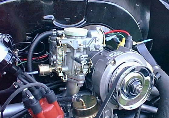 Alternator and Engine Compartment WiringAlternator with External Voltage Regulator Converting from an External VR Alternator to One With an Internal VRWhen wiring your new alternator with an internal voltage regulator, you must disconnect BOTH wires from the (B+) terminal on the old external voltage regulator, but keep them spliced together (they should currently have a double spade connector on the regulator), and then add the red wire from the (D+) on the regulator to make a three way splice. In the process the red wire that WAS on the (D+) gets moved to the (B+) terminal. Since the voltage regulator is now internal, you just bypass the old regulator with the red wires. (You might need to put an small extension in this wire if it's not long enough to meet the other two -- if so make sure it's of similar thickness). All of the red wire is 10-gauge (larger). "Speedy Jim" reminds us that you need to have substantial connectors for this job. In Australia the hardware stores sell 240-volt screw type connectors in either 15amp or 30amp varieties. There are two types -- single hole where the wires are twisted and poked in the one hole and the screw tightened (these usually have a nice soft plastic cover over them -- self insulating), and a block type where you can poke in wires from either end and screw two screws up to tighten each wire. This type has the lower amp rating. I'm not sure what you'd have in the U.S. with your 110-volt standard, but choose the heaviest and it should be fine. The "single hole" type are particulaly good as you twist the wires before poking in the hole. This means the screw just jams the wires together and the brass "bolt" doesn't actually carry much current. In the double ended type, the brass block carries all the current from one wire to the other. My reason for saying this is that the red wires carry up to 50 amps, so the three way splice MUST be substantial. Dont scrimp on this connection - or you could get overheating, and since it's under the back seat, I'd hate to see a fire starting there. The thin wires can be any screw or clip connector, since that carries only a small current. What you end up with under the back seat is a three way splice of the heavy red wires - one gong to the alternator, one across the seat to the battery positive post, and one running forwards through the wiring loom to power the car's electrics (it actually runs up to the headlight switch block, which VW used as a junction box). You also splice the thin blue and green wires together are removing them from the voltage regulator - this provides power to the dash Alt/Gen light. Necessity for the Alternator Warning LightIt is absolutely essential that the (D+) terminal on the alternator be connected to a functioning "Alt" warning light in the instrument cluster. If this light is missing or defective, the alternator will NOT charge the battery! See my hand-drawn wiring diagram above. Also see Speedy Jim's diagram, which is much better than mine! The system is very simple, but it's absolutely critical that you get it right. The (D+) terminal on the alternator MUST connect to a functioning warning light in the instrument cluster. There should be just one wire (blue) from the (D+) connector on the alternator to the button on the bottom of the normal indicator light in the dash. The dash light is also wired from the (D+) (Blue) to ignition terminal #15 on the coil, which in turn is connected to the positive (+) post on the battery (Black). There is no ground wire on the light; the body of the bulb is connected to ground via the light holder (which also provides the ground connection for the other dash lights as well.) The three bulbs (ALT/OIL/TURN) all have a common connection in the socket which also goes to ignition terminal #15 on the coil (which receives power from the (+) post on the battery by way of the ignition switch). The alternator must get a feedback current through the "Alt" lamp in the instrument cluster so it can sense the battery voltage; it uses that as part of the alternator's internal circuitry needed to charge the battery. In other words, with the ignition on but engine off, the indicator light sees 12 volts from the battery (via the same wiring that goes to the ignition terminal #15 on the coil), and nothing on the other side so it glows, but with the engine running, it also sees 12v (actually 14v since the alternator is now spinning) both sides of the bulb - one wire from the battery and one wire from the alternator, so it does not glow. If the alternator dies or the fan belt breaks, there is no voltage on (D+) (looks like ground) and current flows from #15 thru the lamp to (D+), and the "Alt" lamp comes on to warn the driver of a problem. An LED light usually won't work for this purpose. LED's are diodes and will not allow current to flow in the opposite direction. And they use so little current there's no guarantee that there will be enough current flow to excite the alternator into charging. So it's best to stick with the stock BA9 filament bulb for the Alt/Gen light. The 12-volt 2-watt indicator bulbs are available at any VW parts store. The same bulb is used for the speedometer illumination bulbs (two of them) and the other indicator bulbs in the instrument cluster. In a pinch you can borrow one of the illumination bulbs to replace a blown Alt indicator bulb -- the speedometer will be a bit dim on one side but can still be seen until you get a replacement bulb. | ||
|
|