|
||

|
|
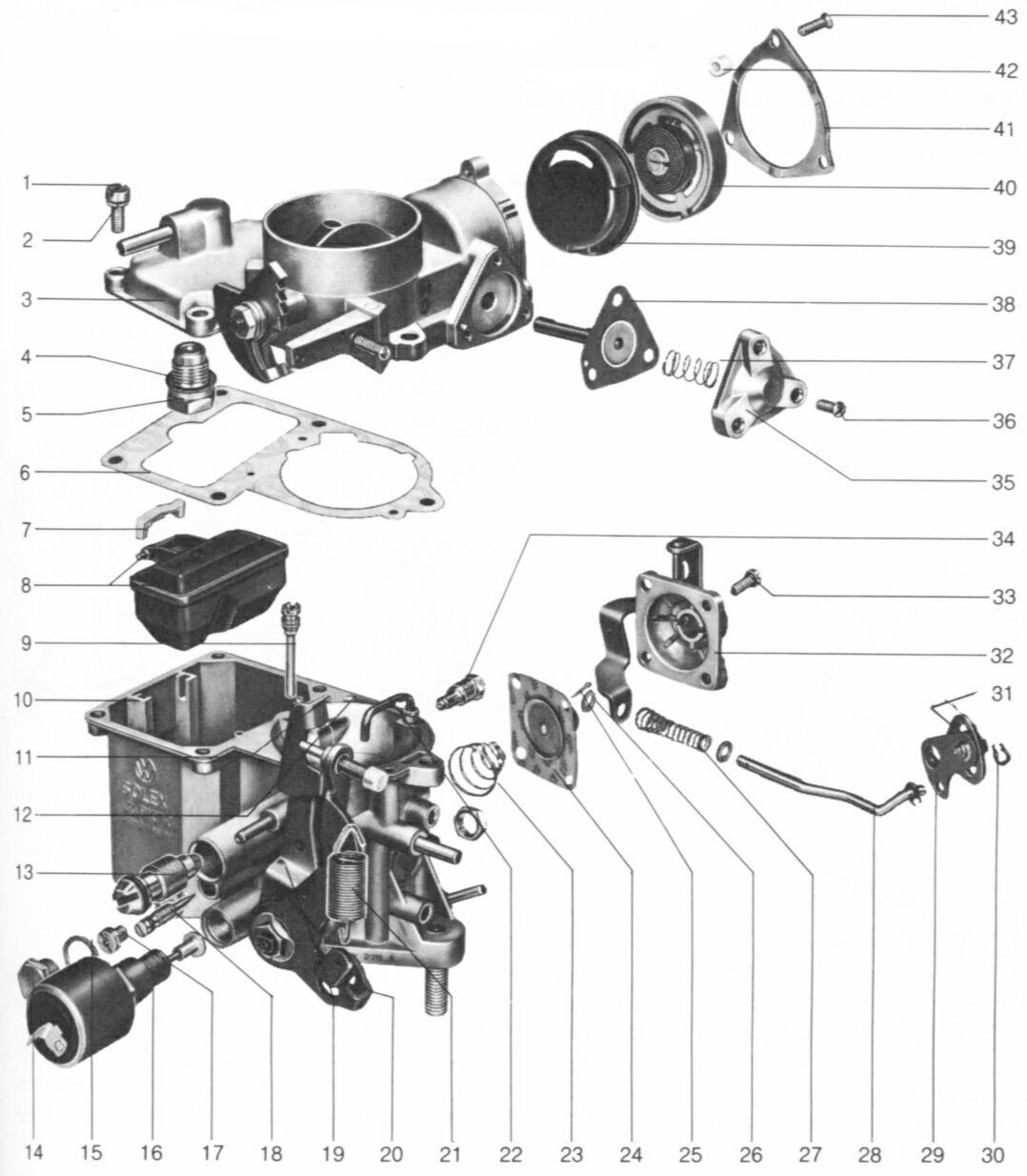
Carburetor Overhaul -
|
|
Ref. No. |
Part |
Ref. No. |
Part |
|
1 |
Fillister head screw and lock washer (upper body (5) |
23 |
Accelerator pump diaphram spring |
|
2 |
Spring washer |
24* |
Accelerator pump diaphram |
|
3 |
Carburetor upper part |
25 |
Cotter pin |
|
4* |
Float valve washer |
26 |
1-mm (.040 in.) thick washer (2) |
|
5* |
Float valve |
27 |
Connecting rod spring |
|
6* |
Gasket, carburetor body |
28 |
Connecting link |
|
7* |
Float pin retainer |
29 |
Adjustable bell crank |
|
8 |
Float and pivot pin |
30 |
Circlip |
|
9 |
Air correction jet with emulsion tube |
31 |
Adjusting segment |
|
10 |
Carburetor body |
32 |
Accelerator pump cover |
|
11 |
Pilot air drilling |
33 |
Screw |
|
12 |
Auxiliary air drilling |
34 |
Pilot jet |
|
13 |
Bypass screw |
35 |
Vacuum diaphram cover |
|
14 |
Main jet cover plug |
36 |
Oval head screw (3) |
|
15* |
Main jet cover plug seal |
37 |
Vacuum diaphragm spring |
|
16 |
Electromagnetic cutoff valve |
38* |
Vacuum diaphram |
|
17 |
Main jet |
39 |
Plastic cap |
|
18 |
Volume control screw and O-ring |
40 |
Choke heating element |
|
19 |
Fast idle lever |
41 |
Cover retaining ring |
|
20 |
Throttle valve lever |
42 |
Retaining ring spacer (3) |
|
21 |
Throttle return spring |
43 |
Small fillister head screw (3) |
|
22 |
Accelerator pump injector |
|
|
*Included in the tune-up kit.
Carburetor Removal
- Before removing the carburetor, check the operation of the idle solenoid cut-off valve. Remove the wire from it, then turn on the ignition (do not start the car). Touch the wire to the electrical connector on the idle solenoid valve. You should hear a distinct "click." If you hear the click, the valve is okay -- otherwise, it must be replaced. Turn the ignition off. This valve shuts off the idle fuel when the ignition key is turned off, preventing the engine from "running on".
- Disconnect the hoses and blow-by (breather) tube from the oil filler to the air cleaner, then remove the air cleaner and set it aside.
- Detach the fuel hose from the carburetor and quickly plug it to minimize fuel leakage (a pencil works great for this).
- Detach vacuum hoses if you have them; if you have no vacuum hoses, remove the caps from the vacuum ports on the carburetor.
- Disconnect the wire to the automatic choke heating element (40).
- Disconnect the wire to the electromagnetic cutoff valve (16).
- Loosen the screw in the accelerator cable barrel clamp, then pull the cable forward out of the pin. Stow the cable ballel clamp and screw in a safe place so you can find them later (small parts).
- Remove the distributor cap to provide access, then remove the two nuts (13mm) from the studs on the carburetor flange. Make sure to have the front nut (front is front-of-car) brightly lit so you can see what you're doing.
Note: Some people use a 13mm S-wrench (ring spanner) to remove the front nut. I find it much easier to just use a regular 13mm box-end wrench (ring sopanner), as getting the S-wrench on and off of the nut is very difficult (walls on the box (ring) end are too thick).
- Remove the carburetor and gasket; there will be a new gasket in your kit, but try to maintain the integrity of the old gasket, "just in case." Stow the two nuts in a safe place.
- Stuff a rag into the open intake manifold to keep foreign material out.
Carburetor Disassembly
- Use the exploded view as a guide. The numerical sequence shown there can generally be followed to disassemble the unit far enough to permit cleaning and inspection.
- Having a small container (like a half-pint glass jar or a plastic ice cream tub - enjoy the contents before your start :-) at ready, remove the main jet plug on the left side of the carburetor and drain the gasoline out of the carburetor bowl into your container. Stow the plug where you can find it.
- Remove the five fillister-head (cheese head) screws that hold the upper part of the carburetor (3) to the body (10) and remove the upper part. Remove the gasket; your carburetor kit should have a new one, but again, try to maintain the integrity of the old one. You never know.
- Remove the float needle valve (5) from the underside of the upper part of the carburetor. There should be a new one in your kit. This valve gets a lot of work -- you should always replace it. (See the note below regarding the float valve in the Pierburg carburetor.)
- For future reference (i.e., reassembly), note the arrangement of the float pin retainer (7) and the float pivot pin (8) relative to the float (8); remove the float assembly and store away carefully. There will be a new pin retainer (7) in your kit; be sure to note which way it goes (see the exploded view). The bow (curve) in the retainer MUST be pointing toward the wall of the float chamber. If the curve is placed towards the float, it will limit the float movement.
- Remove the electromagnetic cutoff valve (16) from the left side of the carburetor with a 17mm wrench.
- Remove the bypass screw (13) and the volume control screw (18) from the left side of the carburetor.
- Inspect the O-rings on the bypass screw and the volume control screw for wear. If they are defective, replace them.
- Reach through the jet plug hole (main jet cover plug (14) was removed previously) with a screwdriver and remove the main jet (17). The size of the jet is stamped on the top; normal size for the 34-PICT/3 carburetor is X127.5 (1.275mm diameter hole). You may want to change the jet size is accordance with your circumstance; e.g., smaller jet size at high altitude (X125 at 4000 ft.). Some engines (mine, for example) like to run a tad rich, in which case an X130 main jet may be appropriate (at lower elevation). The type of distributor (vacvuum or non-vacuum) also affects the size of this jet - see our discussions on the 009 distributor.
- Remove the air correction jet (9)(it screws out vertically anf is about 25mm/1in long).
- Remove the pilot jet (34) (sometimes called the "idle" jet) from the right side of the carburetor. Its the one in a channel heading down to the boottom of the carburettor. Take note of the size and position of this jets as it's easy to mix up with the power (Aux) jet next to it - they will happily screw into each other's position. Remove the little cover and jet that are at the ten-o'clock position from the pilot jet.
- Remove the various other jets and adjustment screws from the carburetor body and store them away carefully. You will clean these and replace them. Inspect all jets, adjustment screws, and the holes they came from for wear.
- Disassemble the accelerator pump (32) and linkage (28) by removing the four screws (33). There will be a new accelerator pump diaphragm (24) in your kit.
- Check the throttle valve shaft assembly for lateral movement (side-to-side) in the throttle shaft. If you find such movement, the shaft hole is out-of-round and you will be getting air in-leakage. This is very serious; it is likely that the rest of the carburetor isn't in very good shape, either. When I discovered this problem I just bought a new carburetor.
- Disassemble the automatic choke assembly (40) by removing the three screws (43) in the cover retaining ring (41). Be careful to make sure the three retaining ring spacers (42) aren't lost.
- Remove the choke vacuum diaphram cover (35) by removing the three oval-head screws (36).
- Remove the vacuum diaphram (38) and spring (37)
Note: You will be removing a number of small parts in this process; hopefully "stow them in a safe place" goes without saying.
Note: Dave found that none of the gaskets in his kit fit his carburetor. So be sure to remove the gasket and store it carefully
Note: Compare the new float valve with the old one. The valve on the Pierburg carburetor has a spring-loaded ball bearing on the end; it is likely that the valve in your kit does not.
Note: The manuals say that you should not remove the volume control screw, as it is set at the factory. Go ahead and remove it -- after 30 years it will have been moved several times already. "Leaving it alone" is fine for a new carburettor but silly when the engines are all at least 30 years old and in different states of health. Same with the carburetors in general, so adjustments become essential. Adjustment directions are given below.
CAUTION: Brass tube type delivery tubes are a push-fit into the carburettor body and should not be removed or they can fail to grab again.
Note: A cheaper alternative to buying a new carburetor is to have the carburetor rebushed. Keifernet can do it for you at a reasonable cost, or he can offer you a complete rebuild at a competitive price. Our last contact with Keith was some years ago. Another well respected and active VW carburettor rebuilder is TIM.
Carburetor Cleaning
- Cleaning must be done with carburetor disassembled, as above.
- Soak parts all metal parts in carburetor cleaning solvent (or lacquer thinner) long enough to soften and remove all foreign material. Use an old toothbrush on the carburetor body.
- Make certain the throttle body (carburetor throat, etc.) is free of all hard carbon deposits. Wash off in suitable solvent, like lacquer thinner, which is basically toluene.
- Blow out all passages in castings with compressed air. Check carefully to ensure thorough cleaning of obscure areas. Do NOT use a wire or similar object to "clean" orifices! The carburettor metal is fairly soft and is easily damaged.
- Make sure all jet orifices and clean and free of obstructions, using compressed air. Again, DO NOT use wire or other objects to clean the jets!
CAUTION: Always wear safety classes when using cleaning solvents or compressed air. Do not allow cleaning solvent to come in contact with skin.
Note: Do not soak the choke heating element, pump diaphragm, float, vacuum diaphragm, or any other rubber or plastic parts in carburetor solvent.
Note: Compressed air is really best if you have it. If not, I find that "canned air" (like Ultra Jet or similar) works pretty well. If you don't have a compressor, talk to Santa Claus! That's how I got mine! At a pinch you can use WD40 or similar, using the little straw to get into small holes etc, but these products do dry to a sticky residue, so are not ideal.
Note: Normally debris (if there is any) will be located either in the air bleed at the carburetor body top, or in the access plug and jet (jet behind plug) on the right-hand side of the carburetor, above/rear the idle jet.
Rob provided further explanation: The idle circuit is behind the main jet - the fuel flows THROUGH the main jet to get to the idle circuit. If you try removing the idle shut-off valve and the air correction jet (the brass bolt head in between the float bowl and the main throat) and the idle jet itself, and then blast air through the passages in both directions, that might get it. You should see some air come out of the progression holes in the carburetor throat just near the throttle butterfly when it's in the closed position.
Carburetor Reassembly
Reassembly of the carburetor is essentially the reverse order of disassembly, giving special attention to the special instructions below.
Replace the Following Parts -
- Accelerator pump diaphragm (24)
- Choke vacuum diaphragm (38)
- Float needle valve and gasket (4 & 5) (See note below.)
- Float pin retainer (7)
- Carburetor body-to-cover gasket (6)
- Main jet plug seal (15)
- Volume control screw O-ring (18)
- Carburetor-to-intake manifold gasket
Special Reassembly Instructions -
- Check the float valve for binding and leakage. It should not be possible to blow air through the valve while the needle is pressed lightly onto its seat.
- Check the float for leaks by immersing it in warm water. That will try to "inflate" the air inside the float. If bubbles appear, replace the float.
- Check the float lever for a worn spot (depression) where it makes contact with the fuel inlet needle valve. Replace the float assembly, if necessary. Be sure to specify the rectangular shaped float Part #8). You can order the float from Aircooled Parts, California Import Parts, Jbugs, Wolfsburg West, etc.
- The proper float valve washer (4) must be used for the specific type of carburetor. The 34 PICT/3 carburetor uses the 0.5 mm (.020") gasket. A micrometer helps to make the distinction.
- Install the plastic float pin retainer (it looks like a plastic version of a paper staple, with a curved spine)with the bow (curve) facing the wall of the float chamber. If the curved spine is towards the float, it will limit the flaot movement.
- When installing the accelerator pump diaphragm (24) and spring, (23) make sure the larger end of spring is properly seated in the carburetor body cavity. Be sure to install the diaphragm with plunger toward pump cover. (See the exploded view.)
- Be sure to use the correct body joint gasket; there will probably be several in your kit. Use the old one for comparison.
- Check the electric heating element (40) in the automatic choke housing for damage. If it is broken, distorted or "kinked", replace the assembly. The element can be checked with an ohmmeter or connected to a correct voltage battery for a few minutes to see if it warms up. (Be sure to ground the inside metal part of the housing in order to complete the circuit.)
- When installing the choke assembly with spring and heater element, carefully rotate the assembly counterclockwise, making sure that the hook on coil end engages with the lever on choke shaft. Continue rotating approximately 1/8 turn more until the index marks align. Then, making sure the three retaining ring spacers are in place, tighten three retaining ring screws securely. (See our Automatic Choke Adjustment Procedure.)
- Turn the volume control screw (18) in until it seats lightly, then back it out 2-1/2 to 3 turns. The bypass screw (13) will have to be adjusted to give the proper idle with the engine running. (See below.)
Note: It is very important that you install the correct needle seat gasket. This gasket sets the fuel height in the float bowl; erratic behavior may result if the gasket is not correct.
Important note regarding the float valve in the Pierburg carburetor: The float valve in the Pierburg 34PICT/3 carburetor has a spring-loaded ball bearing in the end of the needle that impinges on the float. This little ball bearing MUST be in place. If it's not, the float bowl will overfill through the bowl vent down the throat of the carburetor, causing the fuel/air mixture to be WAY too rich - and of course the exhaust will spew out a lot of black smoke and the engine will not run.
Note: Dave found that NONE of the several top-to-body gaskets provided in the kit was the right size or configuration for his carburetor (he was possibly sent a kit for the earlier series carburettors). Make sure the old one you took out stays in good shape so it can be reused. Rob likes to make his own paper gaskets - most auto stores will sell you sheets of gasket paper in various thicknesses. The old one for a pattern and a sharp hobby knife or box cutter works well.
Carburetor Installation
- Install in reverse order of removal.
- Lightly lubricate the choke valve shaft and throttle valve shaft with engine oil and the external linkage with molybdenum grease.
- Using a new gasket, install the carburetor on the intake manifold flange.
- Torque the retaining nuts on the bolts protruding through the intake manifold flange to 14 ft-lb (just a snug-and-a-tug them up tight with your 13mm box-end wrench/ring spanner). Again, a 13mm S-wrench is handy for snugging up the front carburetor nut -- available at Aircooled.Net. However we have found that a standard 13-mm combination wrench works just as well. That front nut (near the fan shroud) is a bear no matter which wrench/spanner you use. Be careful that you don't tighten these nuts too much -- you may strip the stud out of the base of the carburetor. Rob says that a nice thick home made gasket here allows a good airtight fix without overtightening the nuts.
- Secure the fuel hose to the inlet nozzle on the carburetor with a new hose clamp.
- Pass the end of the accelerator cable through the cable pivot pin installed in the throttle lever. Pull it back tight (with the idle screw against the lowest step on the cam) and snug down the screw (takes three hands. Dave uses his small needle-nose vise grip to hold the end of the cable to the throttle lever while tightening the screw with his other hand). See our Accelerator Cable Adjustment Procedure.
- Perform the Idle Adjustment and Timing procedures.
Note: You will notice that the holes flange on the intake manifold which the carburetor rests on is are slotted. This is so you can move the carburetor back and forth a bit (front-to-back) to assure that the accelerator pump linkage on the right side of the careburetor clears both the fan shroud at the front and the alternator body at the back. Both clearances are essential; If the accelerator pump linkage rubs on either end, the throttle lever will not be able to return all the way to the stepped cam, the result being an excessively high idle that cannot be controlled with the bypass screw.