|
|
|
Building Up a Longblock
~~~
Note: This is a VERY LONG procedure.
You would be well advised to read it through in its
entirety to get a feel for what you're going to be doing.
Please see our Lessons Learned article, which documents
some lessons Dave learned during his longblock buildup process.
~~~
Procedures are provided herein regarding things that must be done during the longblock buildup process (these are all links directly to the specific procedure) -
~~~
Dave's old engine finally died (seized up solid during a maximum-advance timing test). Rather than having the engine rebuilt yet again, Dave decided to replace the engine. Not being an engines internal kinda guy, Dave decided to purchase a longblock from Aircooled.Net. The following note is adapted from information provided by Aircooled.Net about the longblock -
Note: This is a new factory VW engine 1585cc (1600cc) upright dual-port dual-relief engine with all new parts... Far better than any "rebuild" available... All parts in the longblock are brand new, not rebuilt. The dual-port engines are a straight swap for 1971 and newer Beetles and Ghias, 1971 T-2s, and 1967 and newer T-3s... You won't believe how much power a "stock" engine has!
These engines are complete from valve cover to valve cover. The longblock includes the oil cooler, but not the cooler adapter. The engine does NOT come with distributor drive pinion (you must install one - though for a small fee Aircooled.Net will install it for you). It also does not include a clutch, pressure plate, fuel system, carburetor, intake manifold, cooling system, ignition, or exhaust parts. The mounting stud for the thermostat is NOT installed nor tapped, but the case does have the boss in place for drilling and tapping to install this stud (we recommend that a functional thermostat be installed).
Solid lifters need to be adjusted just like the engine you have now (set at 0.006" cold). You MUST adjust the valves on these before you run them -- they are always completely wrong!
Since this job could take several days (or even weeks! months?) to complete, it is best to dedicate a section of your workshop to the task, including an area to lay out the parts for inspection and cleaning. An engine stand helps if you can afford it; we've never felt the need for one in the five times we've removed the engine from the car. Lots of large wooden blocks (and a bit of muscle) are almost equivalent to an engine stand.
The tools you will need are simple and found in the most basic of toolboxes: screw drivers, box-end wrenches (ring spanners), a handful of the usual metric sockets, and a 3/8"-drive ratchet will do most of the work that is required. Since the longblock arrives fresh from the factory, it (and some of the new parts) may come with a dousing of Cosmoline, a nasty, sticky petrolatum used to protect the parts from rusting during shipping. The Cosmoline, if it is there, must be thoroughly cleaned off before proceeding.
~~~
Note: Remember - "Front means the front of the car - The flywheel and clutch are at the FRONT of the engine. "Back" means the rear of the car - the engine pulley and fan belt are at the REAR or BACK of the engine.
Note: Keep all of your parts neat and in order so that you'll easily be able to tell what you've got and what you're missing and will have to order. Thoroughly clean and assure the functionality of those parts that will be reused.
Note: You will notice that all of the major holes in the longblock have been covered to prevent debris or dust from entering the engine, possibly causing some major damage. Keep these holes covered until you need them. Nothing is more defeating than dropping a nut down the fuel pump hole!
~~~
- Remove the Engine from the Car.
(See our Engine Removal
Procedure)
- Distributor Drive Pinion -
The supplier may have already installed the distributor drive pinion for you. If not, here's what you do -
- You cannot have the washers on the pinion during the installation (they are too wide). You must put the washers in the case, then slip the pinion in.
- To do this, "level" the pinion by tipping the engine 1/2 side down (3/4 up) slightly, so the pinion hole is vertical.
- Then, grease the washers and put them on a screwdriver; release them and they slide down into position. Use the screwdriver to center them.
- Now put the pinion in. (We recommend ignoring the manuals for this; proper orientation is critical.)
- Place the rotor in the 4 o'clock position. So get the distributor you are going to use and aim the rotor at 4 o'clock. Now hold the pinion on the bottom of the distributor. This is how it needs to end up.
Note: The pinion will rotate around 30 degrees as it slides home, so rotate it back this much before you put it in.
- As the pinion's sliding down, look down the fuel pump hole and make sure it's entering properly with regard to the brass drive gear. Light taps with a drift and hammer will seat it.
Note: You'll know it's fully seated when the pinion is BELOW the oiling window immediately to the right of the top of the pinion. Putting the distributor in will also verify that it's all the way down, since the distributor will have to be flush with the top of the clamp to be fully engaged.
Note: We waited until the new engine was in the car before installing the distributor -- that way we didn't have to move the rotor at all.
- Crankcase Pulley -
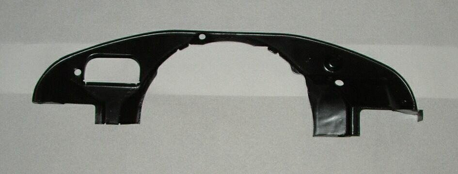
Note: You must install the rear breast plate before you install the crank pulley. If you install the crank pulley first, the two bolts that secure the breast plate to the engine block will not be accessible.
- Install the new engine breast plate with two 10mm bolts that secure it to the engine block.
Engine Breast Plate
~~~
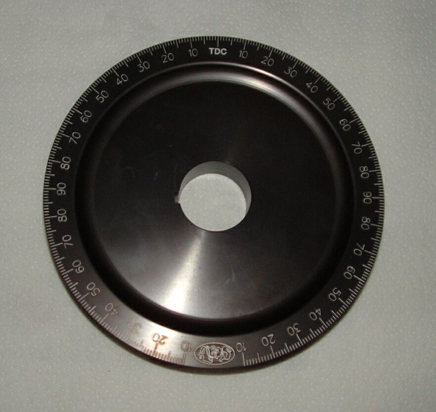
Crankshaft Pulley
~~~
- Install the new crank pulley -
- Clean the nose of the crankshaft. Extra-fine emery cloth can be used to remove dry rust or corrosion. A fine file can be used to remove or repair any burrs.
- Make certain that the key on the crankshaft lines up with the pulley keyway and is firmly seated.
- Simply push the pulley onto the crank as far as you can by hand. It should slide on fairly easily.
Note: It doesn't matter where on the pulley the keyway is. When you turn it so that the keyway is at 9 o'clock, piston #1 should be at TDC, and the TDC mark on the pulley should line up with the crankcase split.
- If the pulley seems tight or does not install easily, follow these steps:
- Immerse the new pulley in very hot tap water until the pulley is hot to the touch. This will expand the pulley slightly, making it easier to slip onto the crankshart.
- Apply a thin layer of "white" grease to the pulley hub serface, then place the pulley on the crankshaft, making certain that the key on the shaft lines up with the pulley keyway and the key is seated on the key in the crankshaft. If you find it necessary to tap the pulley to slide it onto the crankshaft, gently tap the center hub only with a rubber hammer or block of wood. Never strike the outer rim of the pulley.
- Start the crank pulley bolt on the threads on the end of the crankshaft.
- Prevent the engine from turning over by placing a 1-7/16" socket on the flywheel nut, with a 4-foot "cheater" (just an ordinary pipe) against the floor so the crankshaft will not move.
- Tighten the crank pulley bolt using a 1-1/4" socket (a bit large, but it will work). Tightening the bolt down will pull the new crank pulley onto the end of the crank.
- You will install the fanbelt and the pulley tin later. Installation of that tin must be done in coordination with the installation of the air deflector tins, the cylinder covers, the muffler header, and the pre-heat tubes.
- Doghouse Oil Cooler -
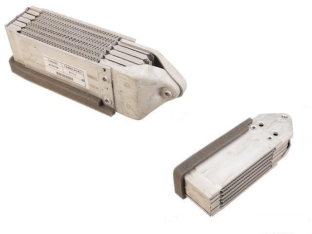
Oil Cooler
~~~
Note: These coolers are sometimes shipped with plastic plugs in the inlets and outlets. These must be removed before final installation (they are there to keep the dirt out). Check the inlet and outlet for any other obstruction.
The oil cooler is installed without using any kind of sealer, which would possibly clog the oil cooler.
- Using an 11mm socket (or box-end wrench - ring spanner), attach the oil cooler to the adapter with two new seals. There are studs to which 10mm nuts are to be attached - two long ones and one shorter one.
Note: The supplier may send you the adapter without these studs installed (the three fatter studs which attach the adapter to the engine block. You will have to install these - it isn't hard).
Note: It is tricky to keep the seals in place while you attach the cooler to the adapter, but with a couple of tries, you can persuade them to stay in place as you put the two bolts through their holes.
Note: Don't be tempted to install the adapter to the engine case first, than attach the cooler to the adapter. It can't be done - the cooler impinges on the lip of the "bell" at the front of the engine. For this reason, it is necessary to install the oil cooler to the adapter before Installing the cylinder cover tin.
Note: If you have installed the cylinder covers, it is very difficult to get at the two nuts on the left side that secure the oil cooler adapter to the engine block. It's best to install the oil cooler and adapter plate before installing the cylinder cover tin.
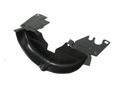
- Don't forget to install the "Hoover bit!". That little horizontal L shaped piece at the bottom of the oil cooler stops used oil cooling air leaking back into the engine compartment - leave it off and your fan will be pulling WARM air in to cool your engine - not a good idea. It's commonly called the "hover bit" after Bob Hoover who was very vocal in stating it's importance.
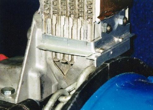
The Hoover Bit
~~~
- Carefully put the two seals in place, then attach the cooler adapter to the engine case with three 13mm nuts on the three larger studs you installed in the adapter earlier.
Note: It is a good idea to feel the mating surfaces for bumps and imperfections, as you'll want a smooth connection to prevent leaks.
- Torque the nuts to 10 ft-lb - do not overtighten!
- Alternator Pedestal -
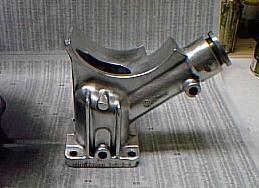
Alternator Pedestal
~~~
- Use a thin coat of a sealer (e.g., Permatex) before placing down the a gasket, another thin coat of sealant, the louvered metal plate (which prevents blowback), another thin coat of sealant, and finally a second gasket.
Note: The louvers in the metal filter should be down with the flat side of the louvers facing the flywheel (toward the front of the car).
- Put a thin coat of sealant around the edges of the second
gasket, then install the pedestal over the four uupright studs
in the engine block.
- Secure the alternator pedestal with 13mm nuts and washers. Tighten the nuts securely.
- Fuel Pump -
- If you will be reusing the pushrod, inspect it for wear and damage. Roll it on a flat surface to check for bending.
- Apply sealer to the engine case around the fuel pump hole, then set down the lower gasket.
- Add sealer to the underside of the insulator block, then install the bakelite insulator block with its pushrod guide tube into the fuel pump hole, on top of the gasket.
- Note: If you find the insulating block and it's guide tube too tight to insert easily into the engine case, it should be carefully sandpapered on the outside of the guide section until it slides into the case as a firm but not binding fit. If it is forced down into the case as a very tight fit, it can expand INTERNALLY when hot and grab the pushrod and stop it moving - very annoying to have the fuel pump stop working at a critical time!
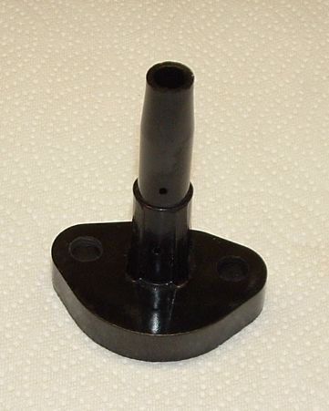
Fuel Pump Insulator Block
(Upside down)
~~~
- Apply some grease to the fuel pump pushrod and then slide it down through the insulator block guide tube, with the pointed end down.
- Apply a thin coat of sealant to the bottom of the top gasket, then place it into position and apply some more sealant around the edges of the top gasket.
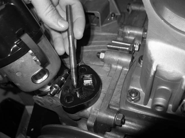
- Check the proper operation of the pushrod as follows:
- With the insulator block, pushrod and one gasket installed (see picture below) -
 |
 |
Fuel Pump Pushrod |
Checking Pushrod Length |
~~~
- Rotate the engine until the fuel pump pushrod is at it's highest point.
- Measure the amount the pushrod is sticking up above the gasket on the flange. This measurement should be 13mm (just over 1/2").
- Next, rotate the engine until the pushrod is at its lowest position.
- Measure how much of the pushrod is sticking up past the gasket on the flange. This measurement should be 8mm (5/16"). The amount of pushrod stroke you are looking for is between 4 and 5mm (1/4")
- See the note below regarding adjustment of the pushrod stroke.
- Fill the lower chamber of the new fuel pump (where the operating lever is located) with universal grease.
Note: This is the lower chamber in the fuel pump you are filling with grease, not the hole in the engine block where the pushrod and its guide tube reside.
- Set the fuel pump in place over the studs and tighten it to the case with two 13mm nuts. Torque the nuts to to 18 ft-lb.)
- Reconnect fuel lines - on the squat round fuel pumps, the top port on the fuel pump is the inlet from the fuel tank; the bottom port is the outlet to the carburetor.
Note regarding pushrod stroke -If you find that there is too much stroke, add gaskets to the top of the flange. If there is not enough stroke, lay a piece of sandpaper on a flat surface and sand the flange a little at a time until you attain the measurement you are looking for. Keep in mind, you need at least one gasket between the flange and the fuel pump.
You can also check to see if your fuel pump is properly shimmed with the correct amount of gaskets by connecting a fuel pressure gauge to the output of the pump. The pressure should read between 1.5 and 3.5 psi of pressure through the normal RPM range. The fuel pressure will be too high if the pushrod is too high. You lower it, as indicated above, by adding gaskets between the pump and spacer. You want 3-3.5 psi.
Rob's note: Although it is commonly stated that adjusting the stroke will alter the fuel pressure, this is not strictly speaking true. Inside the fuel pump is a diaphragm which is pulled downwards by the pump operating arm. This fills the pump with fuel. The diaphragm has a spring which then pushes it back upwards, pushing fuel out to the carburettor. THIS SPRING provides the actual fuel pressure, not the operation of the arm. So if you reduce the stroke (raise the pump with more gaskets) you reduce the VOLUME of the fuel flow, since less fuel is drawn into the pump, but that diapghram spring still pushes it back upwards with the same pressure. Of course if the fuel FLOW is restricted to the point where it is stuggling to fill the float bowl, then the pressure will be reduced as a consequence. This method of operation makes the pump self regulating - if a small fuel flow is required, the diaphragm will not move much, so the operating arm will only just barely get touched by the pushrod at the very top of its stroke, but if a high fuel flow is required, diaphragm will move more as more fuel exits the pump for the carburettor, the operating arm will drop further, and so the pump rod will create a larger movement of the operating arm and diaphragm for more fuel flow, all the while that internal diaphragm spring is maintaining the same internal fuel pressure.
You can test this for yourself - with the pump off the engine but the fuel lines all connected, push the operating arm up with your finger - it might take a few strokes to fill the carburettor float bowl, but it will then stay "up" inside the pump because there is no more fuel flowing to the carburettor - but if you then remove the fuel line from the carburettor, see fuel flow out - the pump is not connected to the pushrod since it's not mounted on the engine, yet there is fuel pressure from inside the pump pushing the fuel out. That's the diapragm spring is inside the pump moving - not controlled by the pushrod at all. But as the fuel flows out, you'll see the pump operating arm descend, allowing the pushrod to do it's job once the pump is mounted on the engine again.
- Heater Boxes -
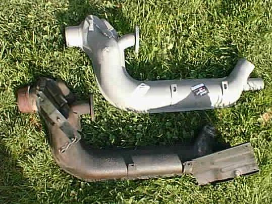
Heater Boxes (Old and New)
~~~
- Before installing the heater boxes on the engine block:
- Cut off the tabs on the top of the heater boxes, as they are not needed and with hit the underside of the car once the engine is in place.
- Work the heater box mechanism to make sure all of the parts are moving freely.
- Support the engine directly under the engine case so the attachment points at the sides can be accessed for the heater box brackets.
- At the rear of the engine, install the flange gaskets (dry) onto the cylinder head mounting flanges for the heater boxes.
- Position the heater box on the two studs in each of the cylinder head mounting flanges. Install the mounting nuts and tighten them loosely for now so that the entire exhaust system can be easily fitted up. The nuts will be securely tightened later. Don't forget to snug these nuts up securely once the whole exhaust system if fitted up! Failure to do so will make the task extremely difficult later, with tin and the header in the way.
Note: There is a left and a right for the heater boxes as well, so make sure to note which is which - the pull-wire mechanism is located toward the center of the car in each case.
- Attach the flexible body-to-heater-box couplings to the heater boxes and secure with hose clamps on both ends.
- Attach the heater box brackets to the underside of the engine case (left and right).
- Engine Tin -
Note: Before installing the fan shroud, the doghouse oil cooler tin, and the firewall tin (front-most), you must install at least the cylinder cover plates. However, you want to install the oil cooler before installing the left cylinder cover plate; other wise access to the oil cooler adapter nuts is very difficult.
The engine tin is installed as the longblock buildup proceeds not all at once. Make sure all of the fastening bolts are in place and snugged down tight. Heres the approximate sequence
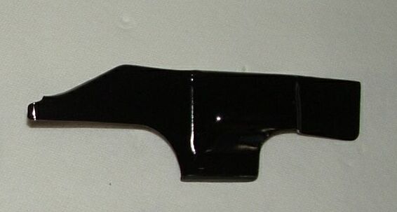
- Rear air deflector plates. These must be installed first - the engine breast plate and cylinder cover plates go on top of the deflector plates. If you fail to do this, the deflector plates will be very difficult to install (that's why most people leave them off - a mistake).
Notes -
- Do not fail to install the two rear deflector tins! These go on the rear of the engine, under and to the left and right of the engine pulley. They should attach to the tinware that covers the cylinders, and they form the rear bottom section of the cylinder cover so the cooling air has to travel to the bottom of the finning before turning towards the rear of the car. Without them attached the #2 and #4 exhaust ports get reduced cooling air through the fins around them as the air will spill out to the rear just above the ports.
- From Aircooled.Net - These are the often missing and lost pieces of tin that keep cooling air tight against the head, at the rear of the engine. If these are missing, head temperatures shoot up. Commonly missing because butcher mechanics neglect to install them, or by sheetmetal screws that vibrate loose, and they just fall off. We cant stress enough how important these are.
- You MUST install the rear deflector tins before installing the muffler header. With the header in place, the deflector tins are almost impossible to install.
- The deflector tins each have two captive nuts; the engine breast plate is secured with two bolts through the breast plate on either side, and into the captive nuts in the deflector tins.
- You will probably find it necessary to bend the deflector tins a bit to make them fit. They are equipped with tabs that are supposed to fit around the cylinder fins. Installation of the deflector tins is a bit difficult. The hardest part (for me at least) was starting the bolts through the rear engine tin and into the captive nuts on the deflector tins.
 |
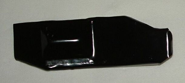 |
Left and Right Rear Deflector Tins
~~~
- Engine breast plate.
- Cylinder cover plates.
Note: The two cover plates are a right and a left, so make sure that you get the correct orientations. You may have to do some minor modification so that the manifolds will clear the lip of the tin.
Again Install the oil cooler adapter before installing the left cylinder cover plate.
- Cooling air channels (following installation of the heater boxes).
- Fan shroud.
- Oil cooler tin and exhaust tin.
- Firewall tin.
- Intake Manifold -
- With a dry intake gasket and 13mm nuts, attach one of the intake manifold end pieces to the appropriate intake port on the cylinder head.
Note: This may be a tight fit; you may have to carefully tap the end pieces in place with a rubber hammer. Since the manifold has to slip under the generator stand, it is easier to do it piece by piece.
- With a new polyurethane clamp, connect the installed end piece with the center piece. Make sure the top of the manifold is level (assuming the surface you are working on is level).
- Bolt down the center piece with the single stud in the center of the engine case.
Note: You may find (as I did) that the bolt (actually a stud) in the engine case (one of several that holds the two halves of the case together) is too short to get a nut on to with the center section of the intake manifold in place. You may need to find a creative way to lengthen the stud so you can secure the intake manifold. You might be able to remove the stud from your old engine block and reuse for this application.
- Attach the other end of the intake manifold to the center piece with a new polyurethane clamp.
- With a dry intake gasket and 13mm nuts, attach the other intake manifold end piece to the appropriate intake port on the cylinder head.
- Securely tighten 13mm nuts on the end pieces and the polyurethane clamps.
Note: The pre-heat tubes may come from the supplier as separate pieces. It may be necessary to bend the tube a bit to make them fit. I installed them into the intake manifold with high-temperature metal repair compound, available at your auto supply store.
- Fan and Alternator -
For
this engine replacement job it isn't necessary to separate the
alternator from the fan. However, it is a good idea to remove
the alternator/fan assembly from the fan shroud.
- To do this, simply remove the four bolts (10mm) that attach the outer fan cover to the shroud.
- Inspect the fan for any defects and clean it as best you can. Painting will add a nice touch (nobody will ever see it, but you'll know it's there and smile!
- Install the alternator/fan assembly into the fan shroud. Make sure the four bolts that hold the outer fan cover to the shroud are securely tightened.
Note: There is a vent/slot on the fan side of the alternator/generator mounting plate that attaches to the fan shroud. This vent is used to cool the alternator -- it draws air through the alternator into the fan housing. The vent, which is on the edge of the backing plate, MUST FACE DOWN in order for cooling air to be properly routed hrough the alternator, otherwise you'll be wondering why you are always destroying your alternator - blaming the alternator rather than the "mechanic" who mounted it.
- With the alternator on the alternator pedestal, install the hold-down strap around the pedestal and the alternator. Tighten the strap snugly (not too tight, as this may cause the fan to rub inside the fan shroud).
- Doghouse Fan Shroud -
- Thoroughly clean the fan and the fan housing, inside and out. Again, painting will make the fan shroud look very nice.
Note:You can use any color you like on those engine parts that are NOT in contact with the hot oil, but for those parts in contact with the engine oil, black is the best color for shedding heat.
- Install the alternator fan assembly into the fan housing. Make sure the four bolts that hold the outer fan cover to the housing are securely tightened.
- Install the doghouse cover and the oil cooler vent (the vent will go through the firewall tin).
- Before attaching the thermostat connecting rod to the cooling vanes, slip it down between cylinders #1 and #2 and make sure it will move up and down without binding.
- On the rear of the engine, reattach the thermostat connecting rod to the right-side cooling vanes.
- Carefully place the doghouse fan shroud down on top of the cylinder cover tin, making sure that -
- The thermostat connecting rod slides properly through the gap in the cylinder head without binding;
- The oil cooler is not damaged during installation of the fan shroud.
Note: There are two engine tin screws on either side of the fan shroud, down at the base, that hold the shroud in place. You may need a flat-head screwdriver to pry open the cylinder tin slightly to accommodate the shroud. (The tin goes INSIDE of the cylinder tin, all the way around.)
- If you have removed the generator/alternator, place the two cover plates back on and bolt them down with 10mm bolts (into captive nuts on the other side). Use Loctite and lock washers, as these bolts aren't something you want to lose inside the fan shroud.
Note: The fan shroud should fit tightly over the cylinder cover tin. Screw it down on both ends of the shroud.
- Slip the alternator strap around the alternator and alternator pedestal tighten the 13mm nut.
- Spin the fan and check for rubbing. You may need to level the fan and alternator by adding a shim between the alternator pedestal and the alternator or loosening the hold-down strap a bit. The result will be a smooth spinning fan that can't rub on the shroud.
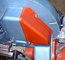
- Install/Adjust the Thermostat -
Note: The following adjustment instructions are for the Mexican-style thermostat.
Note: The mounting stud for the thermostat may not be installed, and the engine block may not be drilled and tapped for the stud. The block does that the boss in place for drilling and tapping to install this stud. DO IT! It is very important to have a functional thermostat installed.
Install the Thermostat -
- Crawl under the rear of the car armed with a large screwdriver, a 10mm wrench, and a 13mm wrench.
- Locate the right heater box. Extending out from it toward the center of the car are two metal tabs, each of which has a screw in it. These attach to a metal plate that has three captive nuts in it. You want to remove this plate.
- Remove the 10mm bolts that hold the metal plate in place. Stow the bolts and washers in a safe place. Note how the metal plate sits so you can replace it the same way, then take it out.
- Feel up through the centre gap in the cylinder head for the connecting rod (about 1/8" diameter) coming down between them. This rod is threaded on the end so the thermostat can attach to it. Move the connecting rod (also called a downrod) up and down to fully open (up) and close (down) the cooling vanes.
- Right above where the metal plate was there is a stud (possibly with a nut on it) sticking out of the side of the crankcase on the bottom of the engine, pointing towards the right heater box. If there is a nut, take the nut off of this stud and save it. If there isn't, you will need to find a replacement in your cache of extra nuts and bolts.
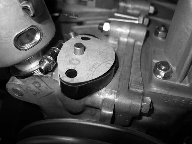
- At your workbench, insert the bottom of the thermostat into the outermost hole in the new mounting bracket, then mark carefully the location of the hole that will accommodate the little protrusion that projects downward on the bottom of the thermostat.
- Measure the width of the little protrusion, then place the mounting bracket in your vise and carefully drill a hole of that diameter at the point you marked on the bracket.
- Screw the top of the thermostat onto the threaded end of the downrod.
- Loosely mount the thermostat into the outer-most hole in the bracket.
- Rotate the thermostat on the downrod as necessary and insert the protrusion on the bottom into the hole you drilled in the mounting bracket. Tighten the nut to firmly attach the thermostat to the bracket and to secure the little downward piece into the hole.
- Note the elongated hole in the mounting bracket. Place this hole over the stud that is projecting from the side of the crankcase. Loosely attach a washer and 13mm nut to this stud.
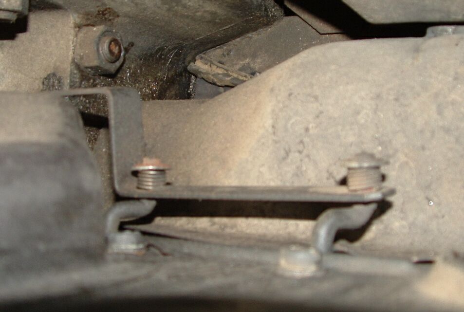
Adjust the Thermostat -
- Pull the thermostat/mounting bracket down to fully close the cooling vanes. Don't pull it TOO tight.
- Hold the mounting bracket at this point and tighten the 13mm nut to firmly attached the bracket to the side of the crankcase.
- Replace the metal plate that goes under the thermostat and between the right heater box and the engine, with the four bolts you took out.
Note: Having that metal plate in place is VERY important -- it helps to make sure that the warmed air passes over the thermostat.
Note: The engine is cold and the thermostat is contracted completely, which means the cooling vanes are closed. Before driving the car any distance, warm it up completely and then have a look at the thermostat -- it should be fully expanded (cooling vanes fully open) directing cooling air down over the engine.
Note: MAKE SURE that the thermostat expands! If not, you could burn up the engine. After driving it a ways you will find that the dipstick is hot, but you should be able to touch it and pull it out without burning yourself. If the dipstick is too hot to touch, the engine is not getting adequate cooling. If this ever happens, reverse the above steps and take the thermostat out. A working engine is more important than warm air in the car!
Rob's note: Just for information, the original bellows style of thermostat will always fail in the OPEN (extended) position - it's designed that way so a failure will provide full engine cooling, rather than restricted cooling. The wax plug style Mexcian thermostat can fail in ANY position, so it's a good idea to have a look at this thermostat occasionally with the engine cold, then hot, just a make sure it's contracting then extending.
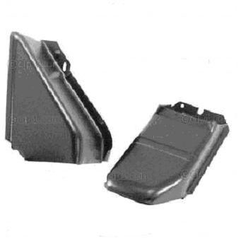
- Oil Cooler and Exhaust Tin -
The exhauster tin must be installed before the oil cooler doghouse tin, as the bolt that secures the exhauster tin to the fan shroud is up inside of the doghouse tin. Make sure the tin is properly fitted around the oil cooler to assure heated air from the oil cooler is being dumped to the outside, not back into the area in front (front means front of the car) of the fan where it can be sucked back into the system.
Note: The doghouse tin fits inside the exhauster tin (i.e., the downspout that dumps hot air from the oil cooler out under the car). The fit is seldom perfect - we fixed this by wrapping some stout, heat-resistant tape (e.g., "Gorilla" tape) around the joint to keep hot air from being sucked back into the fan.
 |
 |
Doghouse Cooler Tin |
The Famous VW Doghouse |
~~~
- Connecting Rod (Cooling Vanes) -
The cooling vane connecting rod is a linkage bar consisting of a flat strip of steel which links the right and left sets of cooling flaps together.
- Install the new connecting link onto the four attachment points on the cooling vane assemblies (two on each side). Put on a washer, then the linkage bar, then a spacer spring, another washer, and finally a circlip to hold the whole assembly together.
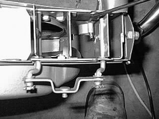
Cooling Vanes Attached to the Linkage Bar
(Looking up into the fan shroud.)
~~~
Vane Attachments
~~~
- Install the new cooling vane return spring between the hole in the fan shroud and the hole in the connecting link.
- Rear Engine Tin
- Remove the bolts by which the rear engine tin will be attached (previously installed for the pulley tin).
- Install the rear engine tin loosely.
- Crawl under the header and with a stylus scratch around the pre-heat connections on the bottom of the rear engine tin.
- Remove the rear engine tin; turn it over and cut around the scratch marks you made with an appropriate tool. Remove this portion of the tin so as to provide access for the pre-heat tubes.
- File the edges of the tin smooth, then paint to prevent corrosion.
- Install the rear engine tin.
- Connect the pre-heat tubes with the pre-heat connections on the header.
Note: Invariably the ends of the tubes and the pre-heat connections on the header will not fit exactly. If your new pre-heat tubes are provided separately from the intake manifold, they can be carefully bent to properly mate with the connections on the header.
Rear Engine Tin
~~~
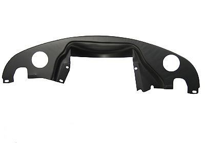
- Firewall Tin(front-most)
- Install a rubber grommet (1/2" x 1/4") in the hole in the firewall tin through which the metal fuel line will pass.
Note: I had a difficult time with this grommet, as I was unable to find a grommet the right size. So I took a piece of the rubber fuel line about 1-inch long, sliced it longitudinally (since I already had the metal fuel line installed), slipped it onto the metal fuel line and urged it through the hole in the firewall tin. Worked great.
- Install the firewall tin, making sure that all of the little clips on the tin are securely in place on the lip of the bell at the rear (front) of the engine.
Firewall Tin
Font size="3" face="Verdana, Arial, Helvetica, sans-serif"> This piece shows the doghouse tinware with the rectanguklar Oil cooler exhaust hole on the left side. The earlier tinware which is used with the "in shroud" oil cooler looks the same, but without that rectangular opening.
~~~
- Starter Motor (only if you are replacing the starter, of course.) -
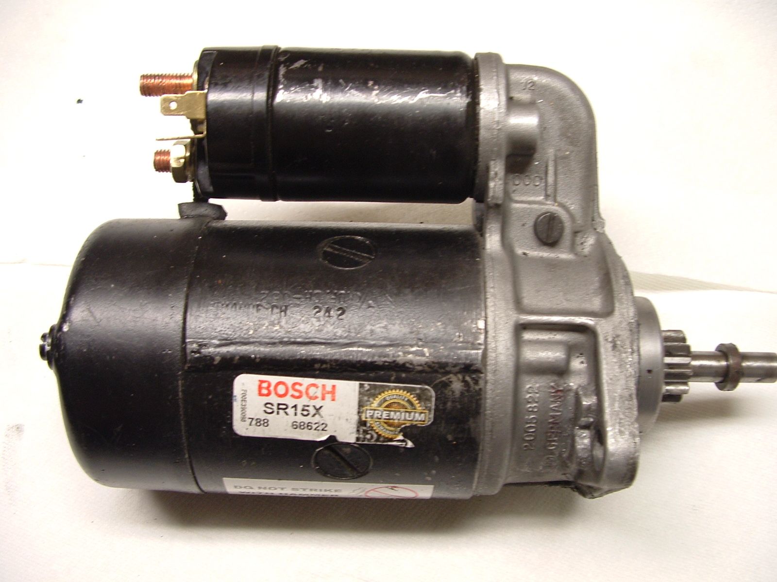
Starter - the side the catalogs show you
~~~
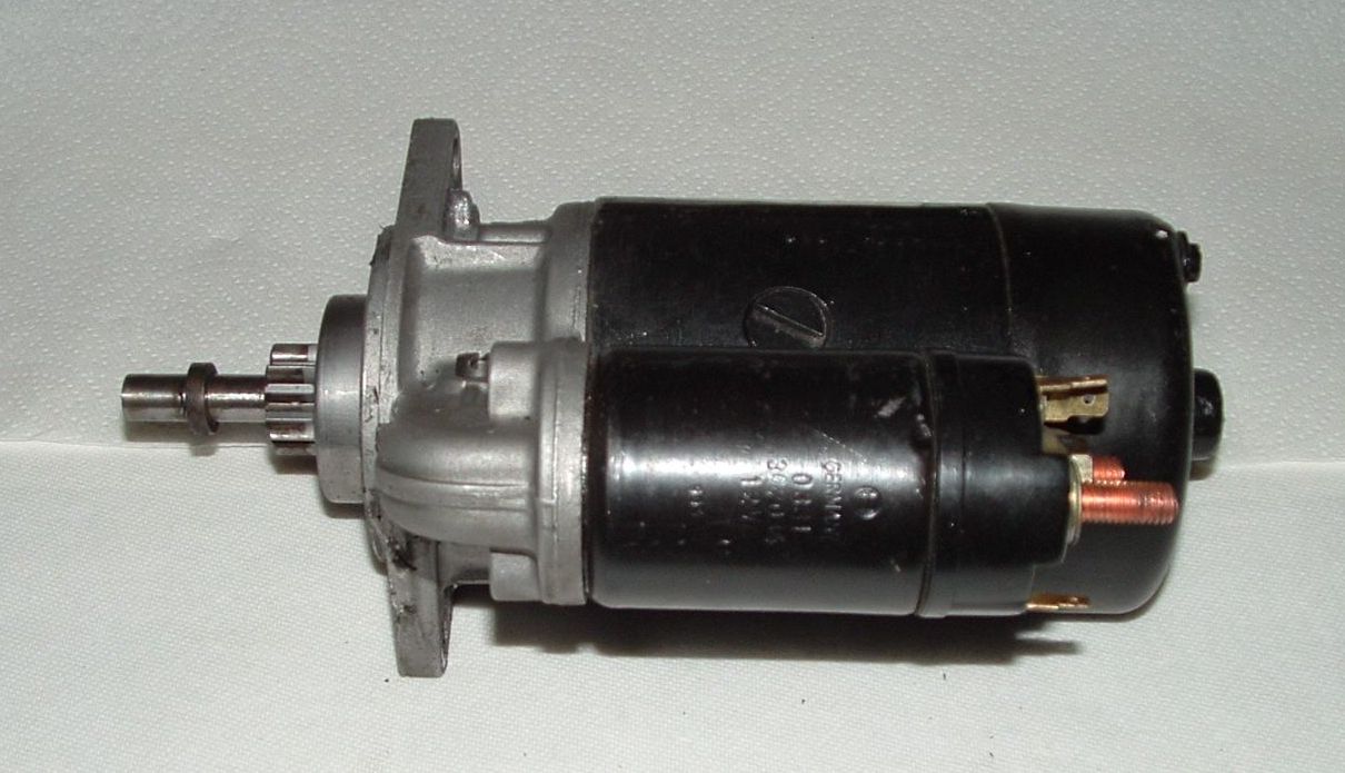
Starter - what you see when installed
~~~
- Disconnect the ground strap from the negative post of the battery.
- Disconnect the wires from the terminals on the starter solenoid (terminals 30 and 50). Carefully
note which wires go where.
Note: The heavy black one is from the battery and attaches to the solenoid on a good-sized stud, secured with a nut. The other smaller wire, (it's supposed to be red) comes from the ignition switch. It has a female spade connector on the end of it and attached to one of the two male spade connectors inboard of the battery connection (NOT the one outboard of battery connection, right in front of you. You really didn't think it would be that easy, did you!?)
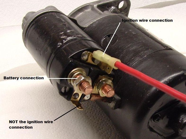
Solenoid Wiring
~~~
- You loosened the starter motor inner bolt when you removed the engine. Now completely remove the inner bolt.
Note the "D" shaped head on the bolt. Explanation below.
- Remove the lower starter mounting nut from its stud, then withdraw the starter motor.
- Inspect the bushing where the tip of the starter fits into the transaxle and replace if necessary.
A note that came with the starter reads -
ATTENTION!
To assure the proper function of this starter, this bushing must be installed into the motor housing prior to installation of the starter itself.
- The bushing must be lubricated prior to installation. Do so, with multipurpose grease.
- Apply a bead of a good sealing compound around the starter opening in the transmission case.
- To reinstall the starter motor (or install a new one if you are replacing the starter motor), slide the starter onto the lower stud and secure it loosely with the nut.
Note: Remember that the top bolt is also the top right mounting bolt for the engine.
- Place the upper mounting bolt (110mm long D-bolt) into its hole and loosely install the 17mm nut on the other side of the firewall.
Note: The long (110mm) inner bolt is called a "D" bolt because the head if flat on one side. This flat side prevents the bolt from turning while you tighten the nut (17mm) on the other side of the firewall. If someone has substituted a regular hex bolt here, you may find it very difficult to tighten the nut, as the bolt will turn as you tighten the nut. And it is VERY difficult to get any kind of a holding device (socket, box-end wrench, etc.) on the head of the bolt. The space is very tight, and the steel-work around the head of the bolt does not allow sufficient space to grasp the head of bolt.
- Tighten the nut on the lower stud; the upper bolt and nut will be tightened when you reinstall the engine. Both connections will be tightened to 22 ft-lb.
- Clean the wires and terminals and make sure the connection points are sound, then tightly reconnect the wires to the terminals on the starter solenoid, as described above.
- Clutch -
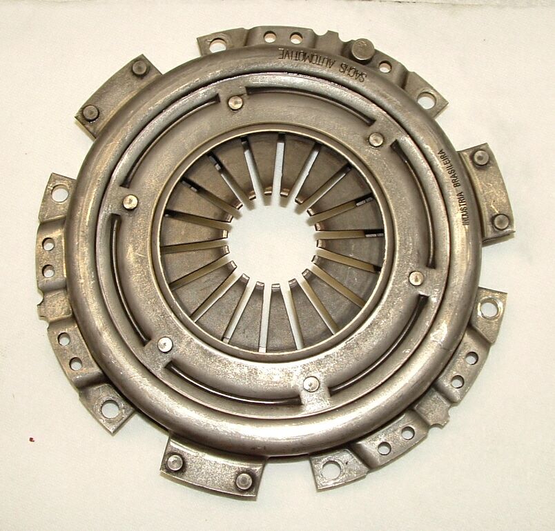
Note: The pressure plate assembly and clutch disk remain on the flywheel when you remove the engine. If serviceable, they will need to be used on the new engine. The clutch release (throw-out) bearing and related parts stay in the transmission.
 |
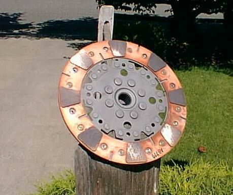 |
Pressure Plate |
Clutch Disc |
~~~
- If you have not removed the clutch from the old engine, do so now, as follows -
- Loosen the pressure plate-to-flywheel bolts by turning each bolt just one turn at a time. Work in a criss-cross pattern until all spring pressure is relieved.
- Hold the pressure plate securely and completely, remove the bolts, followed by the pressure plate and the clutch disc.
Caution: The pressure plate is under a great deal of spring pressure. If you work your way around the plate, removing each bolt one at a time, it will warp.
- Clean the friction surface on the flywheel and inspect it for wear, cracks, heat checking, grooves, and other obvious defects. A polished surface indicates wear. If the imperfections are slight, a machine shop can machine the surface flat and smooth (highly recommended, regardless of the surface appearance). A well machined surface looks like an even flat (non reflective) grey colour, with barely visible circular machine tool marks.
- Inspect the friction surface of the pressure plate for wear, cracks, and grooves. Alternating bright and dull areas indicate a warped plate. Light glazing can be removed with medium grit emery cloth.
- Inspect the diaphragm spring fingers for excessive wear and make sure they are not distorted.
- Shake the pressure plate assembly and verify that the diaphragm spring, which should be under tension, does not rattle. If the pressure plate is defective in any way, replace it. The pressure plate surface, should, like the flywheel, look dull grey and even in colour - a polished surface will allow the clutch friction plate to slip.
- If you will be reinstalling the engine you removed, clean the flywheel and pressure plate friction surfaces with lacquer thinner or acetone to remove any trace of grease or other contaminants.
Caution: DO NOT use oil or grease on these surfaces or on the clutch disk lining. And clean your hands before handling the parts.
- Inspect the clutch release (throw-out) bearing. If it feels gritty when you turn it, or if it has been making noise, replace it. Never wash the bearing in solvent since this will remove the factory-installed lubricant. If the bearing is unserviceable, replace per the procedure.
- Inspect the lining on the clutch disk for wear. There should be at least 2mm of friction material remaining above the rivet heads.
- Check for loose rivets, distortion, cracks, broken springs and other obvious damage.
Note: As mentioned above, ordinarily the clutch disk is routinely replaced, so if in doubt the condition, replace it with a new one. If you're planning to re-use the old clutch disk, it's a good idea to check it for runout.
- Carefully inspect the splines inside the hub of the clutch disk and the splines on the transmission input shaft. They must not be broken or distorted. Lubricate the splines in the disk hub and the splines on the input shaft with graphite or molybdenum disulfide powder (Rob's last replacement clutch plate came with a tiny tube of special "spline" grease to be smeared sparingly on the splines). Then verify that the clutch disk slides freely on the drive shaft splines without excessive radial play. If the clutch disk is in any way unserviceable, replace it.
- Position the clutch disk and pressure plate against the flywheel with the clutch held in place with an alignment tool (the best alignment tool is an old input shaft, or there is a commercially-available inexpensive one made of plastic). Make SURE the clutch disk is installed properly -- most replacement clutch plates will be marked "flywheel side" or something similar. If not marked, install the clutch disk with the damper springs towards the transaxle.
Note Product Instructions from Aircooled.Net -
Clutch Pilot Tool - Using the clutch alignment tool can take a lot of the headache out of installing an engine. Instead of eyeballing to see if the clutch is centered, simply install the clutch alignment tool into clutch disc, and tighten the pressure plate (a turn per bolt, working criss-cross across the bolts). The tool will keep the clutch disc centered so the engine goes onto the trans easier. After you are finished, simply pull the tool out, clean, and save for the next time you need it!
Note: Lacking a centering tool, you can just get down to flywheel height and "eyeball" it. The worst that can happen if it's not exactly centered is that the last inch or so of engine installation might take a little more shoving.
- Install a clutch alignment tool into the center of the clutch disc you intend to use. With the clutch disc on the alignment tool, install the tool into the end of the crankshaft. Make sure that the alignment tool extends through the splined hub and into the needle bearing in the gland nut. Wiggle the tool up-down and/or side-to-side as needed to bottom the tool into the gland nut.
- Make sure that the clutch disc is against the flywheel, then install the pressure plate.
- Loosely start the six mounting bolts in the flywheel. Tighten them "crosswise", back and forth across the plate, turning each bolt a turn at a time, to prevent distorting the cover. After all the bolts are snug, torque them first to about 10 ft-lbs (criss-cross fashion again) and finally to 18 ft-lbs.
- Reinstall the Engine in the Car -
Follow our Engine Reinstallation Procedure.
- Muffler Header -
The following notes are from the "Product Instructions for the Basic Street Header" from Aircooled.Net -
The biggest headache with the installation of this item is getting the old unit OFF the car without snapping the exhaust studs off (which is a huge headache to fix).
(Since we were building up a new longblock, this was not a problem for us.)
The best method for removing the old header is to first remove the rear engine sheetmetal to allow access to the exhaust. Make sure the engine is completely COLD (overnight is best). Spray the exhaust nuts with a good penetrating oil (e.g., Kroil) (WD-40 is NOT a penetrating oil). Now start the engine and let it idle. When the exhaust gets too warm to touch, shut it off and let it cool off again. Spray with more lube. Now the nuts should come off.
The paint on the new header is only there to prevent rust. If you want a nicer finish (and it's not ceramic coated), remove the old paint and coat it with a high temp paint (like our header paint, or BBQ paint, etc).
Here's what the supplier had to say -
Due to environmental regulations, we do not put a durable coating on our painted exhaust systems. The coating used is basically a rust inhibitor and will burn off soon after the exhaust gets hot. We suggest that before installing, you clean off the coating with a good solvent (i.e., lacquer thinner or acetone) and paint the system with a high temp paint, available at most auto parts outlets.
Aircooled.Net goes on to say -
When installing the new unit, use a new muffler kit. Sand the heater boxes down so the doughnuts have a smooth surface to seal against. Normal mechanics rule is especially important here; do not tighten ANY of the nuts or bolts until every single one is on and started, then you can start tightening them up. I suggest re-checking their tightness again in 50-100 miles.
If you are indeed going to be using the heater boxes for heat, new heater hoses must be run from the fan shroud to the heater boxes. With diligence (and patience) the hoses WILL slip on the heater box. It's a very tight and frustrating fit. Do the heater box end first, then slip them on the fan shroud. Don't forget the grommets around the hoses to prevent the rear sheetmetal from chafing and tearing the new hoses.
IMPORTANT NOTE: If you are running a single center-mounted carburetor, the two flanges on the exhaust header MUST be drilled through into the header so that exhaust gases will flow freely through the pre-heat tubes (heat risers) to warm the intake manifold under the carburetor, ensuring that liquid gasoline (e.g., from the accelerator pump) is completely vaporized. Otherwise you could experience a severe stumbling problem on acceleration. The exhaust header usually comes from the parts supplier with the flanges blocked, as they are not needed in a dual-carburetor system.
To install the header -
- First, drill through the flanges on the header that the heat risers will attach to, if necessary.
- Moving to the front of the engine, place the metal gaskets (also dry) on the exhaust ports on the cylinder heads.
- Position the header flanges in place on the studs (two on each side) in the rear cylinder heads and the heat exchanger outlet pipes.
- Attach the header flanges to the rear cylinder heads with four 13mm nuts and washers. Leave the nuts loose until installation of the heater boxes is complete.
Note:Some stretching may be necessary to get everything to line up properly (especially the preheater tube attachments). Make sure to include the gaskets for the heater boxes on both sides.
- Sand the ends of the heat exchanger outlet pipes smoothly so the donuts will have smooth surfaces to seal against.
- Place tightening rings and donut gaskets on the ends of the two heat exchanger outlet pipes.
- Attach the heat exchanger outlet pipes to the flanges pipes on the header with the clamps, bolts and nuts. Before tightening the nuts completely, make sure the donut gasket is properly positioned so as to be held tightly between the two halves of the clamps.
Note: This is a point from which significant exhaust leaks can occur, leaking exhaust directly into the heat exchangers and on into the cabin. Make sure the gaskets are thoroughly compressed and the nuts are tight.
- Sand the manifold ends of the pre-heat tubes to a smooth finish, then install them in the intake manifold using high-temperature metal repair compound or similar.
- Before the sealant sets, adjust the length of the pre-heat tubes to mate with the outlet ports on the header, then bolt the pre-heater pipes to the header using new gaskets.
- Tighten all header connections as tightly as possible.
- Distributor -
Note: There are three things you must align when installing a distributor:
- The drive shaft pulley TDC notch must align with the crankcase split,
- The #1 piston must be at TDC, and
- The rotor must point to the cylinder #1 notch on the rim of the distributor.
- Start by rotating the crank pulley so that the #1 piston is at top dead center (TDC). Check to make absolutely sure using our "straw" test (drinking straw into the sparkplug hole).
Important Note: Since this is a four-stroke (cycle) engine, the crank has to turn TWICE to return cylinder #1 to TDC. For this reason, if you are relying solely on the TDC mark on the pulley, it is possible that the #3 piston is at TDC instead of #1. Thus the importance of the "straw" test to verify.
- Position the distributor clamp exactly over the distributor shaft hole and tighten it snugly on the stud that protrudes from the crankcase.
- Before inserting the distributor, check to make sure that the smaller segment of the drive tang on the bottom on the bottom of the distributor is facing the crankshaft pulley. See the following illustration -
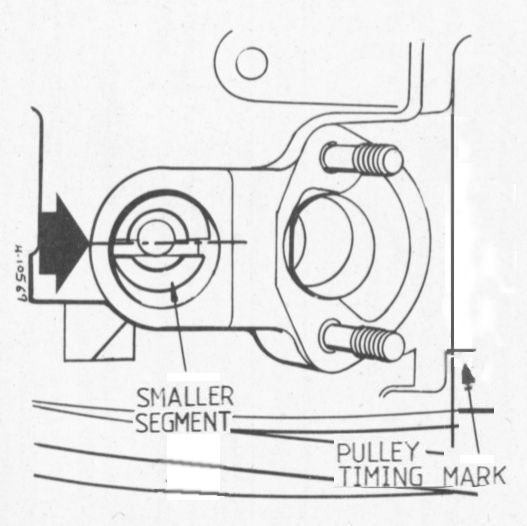
Slot in the Distributor Driveshaft
~~~
- Rotate the rotor so that the tabs at the base of the distributor shaft line up correctly with the slot in the distributor drive and push the distributor firmly into place.
Note: It may be necessary to turn the rotor slightly to mesh the slot in the distributor shaft with the tab at the base of the distributor shaft.
- With the distributor properly installed (the tangs match), rotate the distributor body so that the #1 piston line (notch on the distributor rim) is lined up with the rotor.
Note: The notch in the distributor rim that the rotor points to (with # 1 at TDC) should be at ~ 5 o'clock with a vacuum distributor, or to ~ 7 o'clock with the 009 distributor.
- Time the distributor (SVDA or 009) statically. (See our procedure for static timing.)
Note: If you have electronic ignition installed in the distributor, it will not be possible to time the distributor statically. Cylinder #1 at TDC, the TDC notch on the crankcase pulley aligned with the split in the crankcase, and the rotor pointed directly at the #1 notch in the distributor rim will provide timing that is close enough to start the engine. Then, with the engine running, you should time the distributor with a stroboscopic timing light. (See our procedure for timing with a strobe.
- Tighten the clamp around the distributor.
- Fuel Line -
There are six pieces in the VW fuel line, as follows -
- A short section of rubber/braided line under the fuel tank. (In the Super Beetle, this short rubber section of fuel line may have a filter in it.)
- Metal line that attaches this short section of rubber line under the fuel tank and runs rearwards through the tunnel to the forward end of the transmission.
- A short rubber/braided section connecting the metal line running appearing near the nose of the transmission, to the next section of metal line. This short rubber section allows the engine to rock on it's mounts without tugging on the line (you can't use a solid line from body to engine).
- Final section of metal line near the gearbox and through the firewall, then snakes around the #3 and #4 cylinders (by the spark plugs) on the left side of the engine.
- A short rubber/braided section between the metal line and the fuel pump. This is the right spot to add a fuel filter if you want one easily accessible in the engine bay.
- A short rubber/braided section running from the fuel pump to the carburetor. Many folks place a filter in this location, but it is NOT a good idea as the extra weight of the filter jiggling on the carburettor inlet spigot can dislodge it - if that happens you'll get fuel sprayed all over a hot engine. See our article on the Fuel Filter for further discussion).
Note: Many VW owners have replaced the last section of metal line with a longer rubber line from the body line near the gearbox all the way to the fuel pump. Whether the line is metal or rubber, our concern with fuel safety centers on the hole in the engine tinware through which the fuel line passes. As the engine vibrates during normal operation, the fuel line rubs against the edges of the hole, and over time a hole in the fuel line may develop. With the #3 spark plug and the hot exhaust manifold nearby, this is a major concern for engine fires.
So - here's what we did during our longblock buildup -
- Trim the existing rubber fuel line a few inches beyond the forward end of the transmission (it is this section of fuel line that allows the engine to rock on its mounts).
- Working from the engine compartment, insert the long section of the new metal fuel line through the rubber grommet (and hole) in the left side of the firewall tin.
Note: I had a difficult time with this grommet in the hole in the firewall tin, as I was unable to find a grommet the right size. So I took a piece of the rubber fuel line about 1-inch long, sliced it longitudinally (since I already had the metal fuel line installed), slipped it onto the metal fuel line and urged it through the hole in the firewall tin. I also put a little piece of rubber fuel line around the metal line where it rubs against the pre-heat tube, to prevent rattling. Worked great.
- Insert the end of the new, long section of metal fuel line into the short piece of rubber line near the forward end of the transmission. Secure the rubber section of fuel line to the new metal section with a hose clamp.
- Attach the rear-most end of the metal fuel line to the fuel pump with a short rubber section of fuel line. Secure both ends with hose clamps.
- Run a short rubber section of fuel line from the fuel pump to the carburetor. Again, secure both ends with hose clamps.
- Carburetor -
- Lightly lubricate the choke valve shaft and throttle valve shaft with engine oil and the external linkage with molybdenum grease.
- Using a new paper gasket, install the carburetor on the intake manifold; torque the retaining nuts to 14 ft-lb (just snug them up tight with your 13mm box-end wrench). A 13mm S-wrench is very handy for snugging up the front carburetor nut. Be careful that you don't tighten these nuts too much -- you may strip the stud out of the base of the carburetor.
- Attach the throttle arm spring.
- Secure the fuel hose to the carburetor inlet nozzle with a new hose clamp.
- See the next section for information about the accelerator cable. To summarize - Pass the end of the accelerator cable through the cable pivot pin installed in the throttle lever. Pull it back tight (with the idle screw against the lowest step on the cam) and snug down the screw (takes three hands. I use my channel lock pliers and hold the end of the cable to the throttle lever while I tighten the screw with the other hand).
- Accelerator Cable -
- You will find the accelerator cable dangling under the car just forward of the firewall.
- Push the metal tube that runs through the fan shroud into position, making sure that it properly exits the shroud in front (front is front). Also, make sure that the tube extends through the hole in the firewall. You will be able to see it right about the top rear of the transmission, protruding through the rubber seal.
Note: It is difficult to see the end of the tube protruding though the firewall -- there's so much stuff in the way. It will be above and inboard of the clutch cable. Also, the rubber over the top of the transaxle (especially if it is new) may be in the way and prevent the tube from protruding through. If this is the case, you will have to cut a notch in the rubber with a sharp knife to allow the tube through (easier said than done!).
- Guide the accelerator cable into the tube that is protruding through the firewall. Then flex the guide tube forward and place the flared fitting on the end of it over the tube that is projecting through the firewall.
Note: This is quite difficult, considering that the tube through the fan housing is free to move forward-to-back. If you don't have an assistant to hold this tube in place, fashion a piece of wood to place between it and something else in the engine compartment to keep the tube from moving rearward while you install the flared fitting on the end of the flexible guide tube over the fan housing tube. We placed a little block of wood between the end of the tube, against the fan housing wall, pinned against the vacuum nozzle on the intake manifold.
- Working in the engine compartment, pull the cable through the fan housing tube into the engine compartment, and install the spring and keeper (if so equipped).
- If you disconnected the forward end of the cable for any reason, move to the cabin and reconnect the front fitting on the cable to the accelerator pedal. The S-shaped fitting is inserted through the hole in the pedal lever from the side toward the brake pedal. If you hook it up the other way (i.e., inserted through the hole from the side opposite the brake pedal), it will come apart the first time you put your foot to the accelerator pedal.
- Loosely connect the cylindrical fitting (barrel clamp) on the rear end of the cable to the bottom of the throttle lever, using the clamp screw assembly.
CAUTION: Make absolutely sure that the barrel clamp rotates freely in its two holes at the base of the throttle lever. If it doesn't, it will hang up and cause the accelerator lever to stick, usually at a high rpm. You may be tempted to tap it into place with a hammer, but don't do it! If it's that tight, it won't rotate as the accelerator cable is pulled back and forth, and it will stick. Take the barrel clamp out and polish it with emery cloth until in rotates freely in the holes at the base of the throttle lever.
- Have an assistant fully depress the accelerator pedal while you adjust the cable. With the pedal fully depressed and the cable extended forward, the throttle lever should be wide open and attached to the cable such that there is about 1mm of clearance between the throttle lever and the point where it impinges on the body of the carburetor. It's easiest to simply note where the clamp goes on the cable end in this position (wide open), then let up on the pedal and make the connection with the system relaxed.
Note: The throttle arm should move almost 90 degrees from closed to fully open - when closed it sits almost (not quite) horizontal across the carburetor throat and when fully open it stands vertically in the throat. So if you're getting more movement by pulling on the throttle arm (than the accelerator pedal provides) then the cable is not properly adjusted.
Note: Rob just pulls the accelerator cable back finger tight (NOT with any kind of tool) and then secures it in place with the barrel clamp, and it works just fine.
- Heater Control Cables -
Note: If you'll be relying on the proper operation of the heater boxes for warmth in the cabin, it is critical that you make them work.
Note: The heater cable is really two cables joined together near the control lever.
- Inspect all components for wear and damage and replace as needed. Make sure the flap mechanism and controls are moving freely. Lubricate as needed.
- Working under the car, make sure the cable is well greased. Insert the sealing plugs onto the cables (small pieces of vacuum hose, slit down the side, work well for this).
- Grind off the tabs on the top of the heater boxes. They are needed for Buses, but unneeded on Beetles (they hit the underside of the car once the engine is in place.
- Install return springs between the bottom of the lever assemblies and the engine tin (if your car is so equipped - mine isn't. The return spring is in the heater box valve mechanism.)
- Reinstall the barrel clamps and slip the cables into them. Take up all the slack in the cable and tighten the clamp bolt.
- Have an assistant operate the heater control while you check for full movement of the lever.
- Install the corrugated heat tubes between the heater boxes and the body of the car.
- Alternator Pulley and Fan Belt -
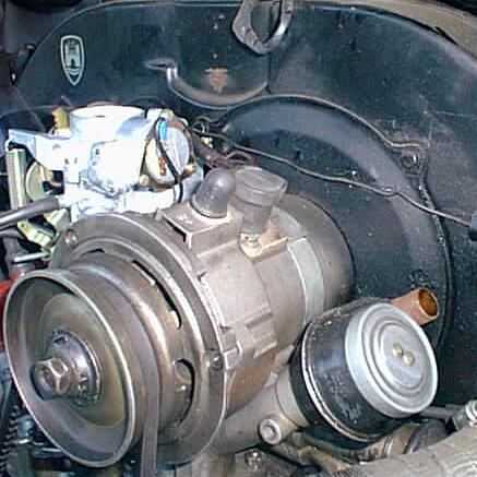
Alternator and Pulley
~~~
Note: The new longblock does not have a pulley installed. If you did not purchase a new pulley, you will have to use the pulley from the old engine.
- If you removed the fan from the shroud (with the alternator attached),now is the time to reinstall it. At your workbench, slip the fan into the shroud and attach the cover with four tin screws and washers.
- Install the hub (inner pulley half) on the end of the alternator shaft. While the hub is slipped on, make sure it is lined up with the Woodruff key and that they key isn't pushed out of alignment.
Note: The Woodruff key slips into the slot on the generator shaft and must be properly seated. This little Woodruff Key is very important to the whole process. If you assemble it without this key, odds are good you'll start spinning the fan hub (which might cause the fan to malfunction) and ultimately damage the engine.
- Install the outer pulley half, placing 10 shims onto the alternator pulley half as a starting point.
- Place the belt into position while installing the other half of the pulley. Install the remainder of the shims, then the bell shaped spacer, and tighten the 19mm nut.
Note: When working with the fan belt, you'll want to have realitively clean hands, as any oil on the belt can cause it to slip under stress.
Set the fan belt tension as follows -
- Rotate the engine a full revolution and check the belt tension. You should be able to push the belt in between the two pulleys 5/8". No more, and no less. If you can move the belt more than 5/8", you will need to remove shims from in-between the pulley halves, and add more if you cannot move the belt 5/8".
Note: Remember to rotate the engine between each fitting of shims to make sure the belt is fully seated before you check it's tightness. Always put any extra shims between the pulley half and the bell shaped spacer for safe keeping for when you need to replace or adjust the belt in the future.
- Wiring -
CDI Wiring -
|
CDI Wire Color
|
Connections
|
|
Green
|
From the distributor to the CDI unit.
|
White
|
From the CDI unit to the positive coil terminal (#15).
|
Black
|
From the CDI unit to the negative coil terminal (#1).
|
Red
|
Power from the ignition switch to the CDI unit, electronic ignition, automatic choke, idle cutoff valve, and backup lights.
|
Separate Black
|
To ground.
|
See the following schematic, which includes the alternator with internal voltage regulator but does NOT show wiring related to the power block described above. Please see the power block diagram above for wiring details.
~~~
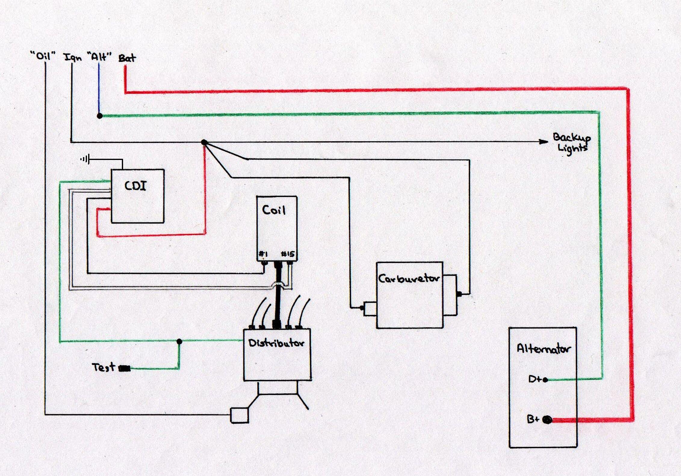
CDI and Alternator Wiring
Note: The wire from the oil pressure switch
to the warning light in the instrument cluster
is blue/green in color.
~~~
Note: Because of the complexities of the wiring in Dave's engine compartment (equipped with both a Capacitive Discharge Ignition (CDI) system and a CompuFire electronic ignition system), Dave installed what he calls a "power block" onto the left fresh-air nozzle on the fan shroud.
There are four positions on this power block -- only
three of them are used. From the top - #1, #2, and #3 - power in from the ignition switch on the left side, and power out to the various places it needs to go on the right side. The connections are discussed below and illustrated in the following Power Block Diagram.
Power Block Wiring -
- Power in side -
- Connection #2 (middle) - Power in from the ignition switch (black wire); jumpers to Connections #1 and #3 (red wires) to provide power to those points.
- Power out side -
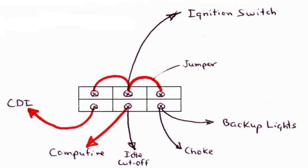
Power Block Diagram
~~~
Alternator Wiring -
- The heavy red wire from the B+ terminal on the alternator runs through the firewall to the battery.
- The green wire from the D+ terminal on the alternator is spliced with the blue wire that runs forward to the "Alt" light in the instrument cluster. This connection is absolutely essential; the car will not run without it.
- Hideaway Muffler
See also our procedure regarding installation of the
Standard Muffler for more information.
~~~
Note from Aircooled.Net regarding this muffler (adapted) -
The Hideaway style muffler is quiet, flows well, and has NO reduction in ground clearance. The muffler tucks up safely under the car next to the #1 & 2 valve cover. For this reason you must remove this muffler to adjust the #1 and #2 valves. A muffler support bracket is required to provide support; this bracket wraps around the header pipe or the heater box on the right side. Sometimes some minor modification must be made to the bracket to fit your engine.
Installation Procedure
- As you did with the header, remove all of the black temporary paint from the muffler assembly with acetone.
- Paint the muffler assembly with black high-temperature paint (two coats).
- With a thick triangular gasket, attached the muffler assembly to the header with 13mm bolts, washers and nuts. Tighten securely.
- Attach the muffler to the header using a clamp (see below) and the tab provided on the muffler.
Note: Since the muffler is oriented on the right side near the right valve cover, I found it necessary to secure the muffler to the right heater box rather than to the header.
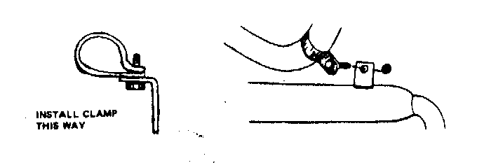
Muffler Attachment
~~~
- Miscellaneous Last-Minute Things to Do -
- Plug the port on the upper right side of the fan shroud with a rubber stopper.
- Install the vacuum line from the distributor vacuum canister to the left-side port on the carburetor.
- Install the fresh air hoses that run from the two large nozzles on either side of the fan shroud to the heater boxes. Carefully cut to length and secure with hose clamps on both ends.
- Reinstall the air cleaner and the crankcase breather tube. Plug the left port on the air cleaner, since the new intake manifold does not have a nozzle to provide vacuum.
- Install a rear engine seal.
Note: John Connolly (Aircooled.Net) recommended a seal that is used in the 1972 and newer Type 2's and in the Type 4 VW. This seal is composed of fairly tightly foam; it is H-shaped in cross section, with the H rotated 90 degrees. The seal is pressed down into the space between the engine tin and the body of the car such that one side of the H is underneath the tin, and the other side runs around the top. The installation is a bit fiddly; it may be necessary to use some weatherstripping adhesive around the back, where the gap is fairly wide, to keep the seal from falling down onto the muffler.
- Reconnect the grounding strap on the battery.
- Replace the wheels.
- Jack the car back up to clear the jack stands. Remove the jack stand pedestals jack stands and carefully lower the car.
- Put 2-1/2 liters of cheap 30 wt oil in the crankcase. You will be changing it after the first 15-minute break-in period.
- Start-up Procedures (from Aircooled.Net) -
Note: The engine may or may not come with cylinder #1 sitting at TDC. Check to make sure using our Finding TDC procedure. The valves were adjusted and the distributor drive pinion was installed by Aircooled.Net.
- Establish Oil Pressure
- Remove the spark plugs and oil pressure switch.
Note: Keep the spark plugs out until later; if they are in, remove them. The reason the spark plugs and oil pressure switch are removed (or left out) is that you do not want the connecting rod or main bearings "loaded" during the "dry" period that exists before oil pressure is achieved. It is only after oil pressure is achieved that the spark plugs should be in place during cranking.
- Prime the oil pump with a few squirts of oil into the pump outlet (by way of the hole for the oil pressure switch.
- Remove the fuel line from the carburetor and place the end in appropriate contain to catch the gas that will squirt from the fuel pump during cranking.
- Get into the driver's seat and put the key in the ignition. Crank the engine over until oil squirts out the oil pressure switch hole and gas squirts out of the end of the fuel line.
- Install the oil pressure switch, and connect the oil pressure switch wire.
- Continue cranking until the oil indicator light in the instrument cluster goes out, then continue cranking for another 10 seconds or so. The oil system of the engine is now ready.
- Install the Spark Plugs and Set the Timing
Note: Always remove the spark plugs with the engine cold. When hot the hole swells inwards and the plug swells outwards, resulting in a tight plug thread and the risk of galling the threads.
Things you will need to install the spark plugs -
- Two 13/16-inch spark plug sockets - one with a rubber insert to hold the plug, and one without.
- A ratchet (3/8-inch drive).
- A 3-inch extension, 3/8-inch drive.
- A universal, 3/8-inch drive.
- A 6-inch length of rubber breather hose, 1/2-inch ID.
- Set the gap between the bottom bent electrode and the center straight electrode to 0.028" using the feeler gauge on the gapping tool. The bent electrode can be carefully bent in and out with the gapping tool to make the adjustment.
Note: The spark plug gap increases as the plugs wear. John Connolly at Aircooled.Net likes to start with a new plug gap of 0.025". After 10,000 miles that gap of 0.025" will be closer to 0.040". It is better to run the plugs toward optimum then away from it.
- Before installing the new plugs, make sure that the screw cap on the top of the spark plug, and make sure that there is a gasket on each plug.
Note: Whether the screw cap remains on the top of the plug depends on the spark plug wire connectors. With some it is on; with others it is off. With our new spark plug wires, the cap must be on.
- Slip the 6" rubber breather hose onto the WIRE end of the plug.
Note: The rubber hose is used here so you won't drop the plug somewhere you don't want it (like inside the tin. Ideally the hose will grip the plug, but you will still be able to turn the plug.
- Using the hose as a "socket" extension, hand-thread the plug into its hole. Do your best to flex the hose as necessary so the plug aligns properly with the plug threads.
Note: The plugs should start in the holes and turn fairly easily by hand. But please note - The cylinder heads are soft aluminum, so be careful you don't cross thread the plugs when screwing them in. Always start the thread by hand for a turn or two so you can tell if it's cross threaded before any damage occurs (there's just enough room to hold the threaded top of the plug in the hole in the tinware). This is one reason why it is wise to use a rubber hose on the plug - if the plug does cross thread, the hose will slip and it won't hurt anything.
- Once you are confident that the plug is started well in the hole (you can feel it), pull the hose off, put on the ratchet and socket WITHOUT the rubber insert (and the 3-inch extension and universal as necessary). Torque the plugs to 22 ft-lb with the engine no more than warm. Never over tighten the plugs -- a snug-and-a-tug should do it.
Note: You do not use the socket with the rubber insert to tighten the spark plug, as the spark plug may be quite tight in the socket, and removing the socket from the spark plug may be difficult. Some people apply some silicone grease onto the plug before putting it in the socket; this will make removal of the socket much easier. Just be sure to wipe the grease off the end of the plug before installing the spark plug wire.
- Put the plug wires on, making sure that the wire on the #1 position on the distributor goes to spark plug #1 -- #2 to #2, etc. Make sure the rubber seals are pushed down firmly on the spark plugs and that the seal is seated properly in the hole in the tin.
- Set the ignition timing on the engine to the proper setting for the distributor you are using This timing is done statically, of course, if you have an 009 or SVDA distributor. See our Static Timing Procedure.
- Make sure you have fuel pressure (see our fuel pump test), and spark to the spark plugs. Go around and check all connections one more time.
- Fire it up (see next).
- Run the Engine!
- This next step is VERY IMPORTANT! Start the engine and immediately bring the rpm's up to 2500 rpm. Vary the engine speed between 2500 and 4000 rpm, and do this for 15 minutes while keeping your eyes glued to the oil light -- if it comes on, immediately shut off the engine and determine the cause of the low oil pressure. The reason for this "high speed" run is to "set" the flat tappets and camshaft so they do not wear prematurely. Since the engine is not under load, it does not harm other parts of the engine at all.
Note: A second person back at the engine looking for oil or fuel leaks is a REALLY good idea too, since you don't want a fire or a VW version of the Exxon Valdez in your driveway! Most oil leaks will occur very soon after startup, if at all. Now, this is a nerve-racking experience to have the engine at these rpm levels when it's NEW (it sure seems loud!), but if everything is OK, it's going to be fine. Remember that this engine is not even under a load, so it's not a big deal. Minor smoking is normal, all that oil and stuff is all over the inside of the exhaust, and outside the cylinders and heads, is burning off as it gets hot.
- After the 15 minutes has elapsed, shut down the engine, and change the oil.
- When you fire the engine up the next time, you can let the engine idle and make any necessary carburetor and timing adjustments. (See our Tune-Up Procedure).
- Now that the cam break in is completed, you want to REALLY heat the engine up by driving it hard! This loads the rings and will break the pistons, cylinders, and rings in together. Find a hill and drive full throttle up and down a few times, in a gear that loads the engine (usually 3rd or 4th gear).
Note: The loading and extra heat burn the glaze off of the cylinders and allows the rings to get seated and everything else to seat together well. Engines that are missing the cooling flap assembly or thermostat have a tough time seating the rings in, as the engine never gets hot enough. Some engines never break in.
- Repeat the oil change and adjust the valves at 500 miles, and then resume the normal maintenance schedule.
~~~
Now for some explanation! (Provided by John Connolly, Aircooled.Net).
The reason for the varying of engine rpm at initial start-up is that the VW flat four engine does NOT adequately oil the camshaft lobes and lifter heads at rpms below 2500. The oil for the cam-lobes comes from oil sprayed off the connecting rods! If the engine is run below 2500 rpm for too long, the cam and lifters do NOT break in together properly (since they don't get enough oil) They get enough oil for running, but not break-in. In addition, you also run the risk (the higher valve spring pressures you run, the higher the risk) of one or more of the cam lobes getting scored and even going flat. The cam and lifters must work together under a moderate load (valve springs), to allow the metal to work harden before extreme loads are placed on them.
Maintenance Schedule -
Schedule oil changes every 1000 miles (if you have no oil filter) and every 3000-5000 if a filter is present. Do valve adustments to spec every 3000 miles (it does not take long, nor is it difficult) on old engines, and every 500 miles (until adjustments "settle down") on newer engines. Keep a record of valve clearances at every valve adjustment; when a valve gets "abnormally tight" compared to the rest of them for 2-3 valve adjustments, it's a warning sign that the vavle is stretching and is ready to fail! Valve job time (and replace exhaust valves)! At 500-1000 miles, during the 1000 mile valve adjustment, you need to check the rocker SIDE PLAY, and re-shim if needed to .005". Usually this only has to be done once and you are finished with this adjustment.
*
* * * *
|
|