| |
|
|
|
|
|
|
Pushrod Tube Replacement
~~~
- Remove the valve covers.
- Study carefully the arrangement of the rocker arm assembly, the valves and the pushrods so you'll know how they are to be put back together. (See the picture below.)
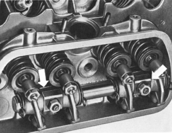
Rocker Arm Assembly
During installation of the rocker arm shaft, the slotted side of the support (left arrow) should point upward. The beveled end (right arrow) shouuld be away from the cylinder head.
~~~
- Remove the two rocker shaft mounting nuts (see above). Loosen each nut a little at a time, working alternately to relieve spring tension evenly. These are special copper plated nuts; keep them separate from any others.
- Pull the rocker shaft assembly off the studs.
- Remove the silicone rubber stud seals.
Note: These seals were eliminated beginning with the 1977 models. Consequently the seal recesses in the cylinder heads, including replacement heads, have been discontinued.
- Withdraw the pushrods from the pushrod tubes and store them in an organized manner so they may be reinstalled in the same place. Before reinstalling them, roll them on a flat table to see that they are not bent. If a pushrod is bent, it must be replaced.
- Using a large screwdriver, pry out the defective pushrod tube(s) from the backside. Remove the old pushrod tube seals and wipe clean the recesses in the cylinder head and the crankcase (where the two ends of the pushrod tubes fit).
- Install new seals on the new telescopic pushrod tubes. Then squeeze together each telescopic tube and install it so that the small-diameter end is toward the cylinder head.
- Install the pushrods into the same positions from which they came.
- Install new silicone rubber seals on the rocker arm shaft support studs (if there are recesses for the seals -- they may not be there if your head has been replaced).
- Carefully guiding the pushrods into the rocker arm sockets, install the rocker arm shaft assembly on the cylinder head.
Note: Be sure that the rocker arm shaft supports have their slotted sides up and beveled ends outermost, as shown in the picture above.
- Loosely install the rocker arm shaft nuts. Tighten each nut a little at a time, working alternately in order to compress the valve springs evenly. Torque the nuts to 14-18 ft lb.
- Do the other side!
*
* * * *
|
|
|
|
|
| |