|
||

|
|
Capacitive Discharge Ignition (CDI)The following subtopics are included in this treatise -
For electronic ignition (e.g., CompuFire) see the following -
Introduction/DescriptionA conventional induction ignition creates a spark by applying electric potential (12 volts) to the primary side of the coil. The coil steps the primary potential up to as much as 18,000 volts and delivers this high voltage to the spark plugs. However, this "step up" process is relatively slow, and as crank speed (rpm) increases, the secondary voltage declines dramatically. This limitation was partially solved by the development of capacitive-discharge ignition (CDI) systems. Instead of applying 12 volts to the coil, a CD ignition increases the primary current by storing it in a storage device called a capacitor. When triggered, the capacitor fires a high voltage to the coil, and the secondary voltage is dramatically increased. The principal advantage of a CDI system is the ability to present a superior spark to the air/fuel mixture inside the combustion chamber, thus maximizing burn efficiency. The easiest way to get a bigger spark is to increase the spark plug gap size. However, increasing the gap distance also increases the voltage necessary to ionize the air/fuel mixture. And the resistance of the air/fuel mixture increases as the mixture is pressurized in the cylinder, requiring even higher voltage to spark across a plug. A CDI system provides the higher voltage required by the increased spark plug gap size, thus providing very intense spark. A CDI ignition system can create spark potential as high as 37,000 volts. Most engines only need about 18-20,000 volts for reliable ignition. The stock system begins to 'droop' as the rpm goes up. At highway speeds, the spark voltage becomes more and more marginal, and can drop below 18,000 volts. With a CDI system, the step up process is very fast compared to a conventional 12-volt induction. This assures a more consistent spark delivery across the plug gap, even at very high crank speeds (rpm). Note: The consistently higher voltage will cause neoprene-type insulation to break down rather rapidly. You need sparkplug wires with better insulation, such as silicone or non-metallic. The carbon conductor in the non-metallic leads will produce less radio interference and won't corrode like metallic leads. Electrically, if you've got 37000 volts available, the ignition system can't tell the difference between metallic & non-metallic leads. We recommend NGK spark plugs, gapped to 0.040 inch. (See our Tune-Up Procedures for more detail regarding spark plug removal and reinstallation. B5HS plugs for the "short thread" cylinder heads, and B5ES for the extended reach cylinder heads work very well. These are stock copper-core and steel spark plugs - save the Platinum and other "special" spark plugs for engines designed to use them. Note from Bob Hoover -- The CDI module doesn't claim to be anything special, just a good basic ignition system. If all you want is a good, reliable ride, it's the best idea since beer in cans. It will save you money, help clean up the environment and make your car run better, all at the same time. Rob wrote regarding the CDI system - The CDI ignition kit DOES help with cold starts and produces fractionally better fuel economy. The plugs DO last longer too. The CDI kit I built many years ago worked well with the standard plug wires, but I suppose the more modern ones would need better wires for the higher voltages they generate. A Bob Hoover Sermonette on CDI SystemsTwo types of CDI units are offered -- a points-triggered CDI module and an optically-triggered or Hall Effect CDI module. VW distributors are not well sealed. There is always some amount of oil vapor inside the unit. Combined with the carbon granules that wear off the central button in the distributor cap, over time this obscures the IR pickup on the optical sensor and results in misfires. It doesn't happen suddenly -- you get some warning that things aren't working right -- and a Q tip (cotton bud) soaked in alcohol cleans it right up. But there are plenty of times, such as when you're in freeway traffic, when you just can't afford to have your engine start missing. The points-triggered module is designed to trigger off the stock points and works equally well when triggered by an electronic switch that uses magnetic sensing (Hall Effect sensor), such as the Pertronix. The basic circuit in the CDI module -- the 'singing aluminum brick' you mount on your firewall or wherever, stays the same no matter what method of triggering is used. The two modules (points-triggered and optically or Hall Effect -triggered) are not interchangeable without going inside the unit and resoldering some wires. The stock points work okay for triggering the unit... sorta :-) The points never wear out since the triggering signal is only about two hundred and fifty milliamps (a quarter of an amp) as compared to 10 or 11 amps in the stock system. But the rubbing block wears down and you have to regap the points every 25,000 miles or so. A thin dab of grease on the points cam occasionally reduces the rubbing block wear, and keeps the points gap correct for longer. And as the miles build up the spring on the points weakens and you start to see points bounce, even at fairly low speeds. But points are inexpensive, robust and universally available making their use practical. I started using CDI modules in the 1960's and used the stock points for triggering until something better came along. As a final note, a lotta guys go to a CDI module because they are having ignition problems and sure enough, the problem goes away once the unit is installed. You'll hear this same story from guys who merely replace their points with a Pertronix or other brand of electronic switch. But the odds are, the problem would have gone away with a good tune-up or rebuilding the distributor, which needs its seals replaced about every 50000 to 70000 miles. If your distributor needs an overhaul, the mainshaft will be loose and that looseness will cause excessive 'hunting' -- the spark won't always occur at the proper time. A CDI module will trigger reliably with a point gap that's too small to measure (!), meaning it will even trigger reliably (although not accurately) with a distributor that is virtually worn out. By the same token, replacing the points with some form of magnetic triggering often masks that wear. Your distributor is still worn out and should be overhauled or replaced but the 'hunting' will have vanished -- right up until the mainshaft binds or the dog gear breaks off or some other catastropic failure occurs. There's no such thing as a free lunch :-) Installation QuestionsQuestion - Soon our Bug is going to have a silver finned box mounted on the fan housing to boost the voltage in the ignition system. The instructions say to mount it as close to the coil as possible -- is it OK to drill a couple of holes in the fan housing and mount it with the sheet metal screws that are provided?) Rob responded - You could put it on the fan shroud -- it wouldn't worry the shroud at all, but that means it will be subject to engine vibration. Another good place is on the left side of the firewall, near where the wiring harness comes into the engine bay. This has two advantages, it gets less vibration, and it's in the path of cooling air being sucked into the fan through the grills above. You just need self tapping screws long enough to penetrate the firewall padding, but not so long they poke through the carpet/felt on the inside. That means the finning will get some useful airflow over them. It DOES run hot, that's the nature of the beast. That's what finally killed my home-built kit off, several of the components slowly cooked themselves, and it wasn't worth fixing it up. My version had a plain box (no fins) with the power transistors mounted to the box itself. They were OK, but several components inside the box cooked. Hopefully the improved layout of commercial units like yours, with the finned box, will stand up better. Had I known, I might have tried putting air holes in the sides of the box to draw some cooling air through it. CDI Installation ProcedureNote: The firewall is ribbed for strength, so you might find some screws go in further than the others before touching the firewall. Note: John Connolly (Aircooled.Net) says "If you have a high-output ignition (e.g., CDI), here's a tip. Some Bosch rotors have a resistor between the middle and end, under the epoxy. High output igntions WILL burn this out, resulting in you tearing your hair out trying to find the cause of the misfire. Dig it out, and then braze a piece of brass in place of the resistor. Fresh epoxy will finish the job nicely. NO MORE MISS." Modified rotors for high-energy systems are available from Aircooled.Net. CDI Wiring
See the following schematic, which includes the alternator with internal voltage regulator but does NOT show wiring related to the power block described below. Please see the power block diagram below for wiring details. 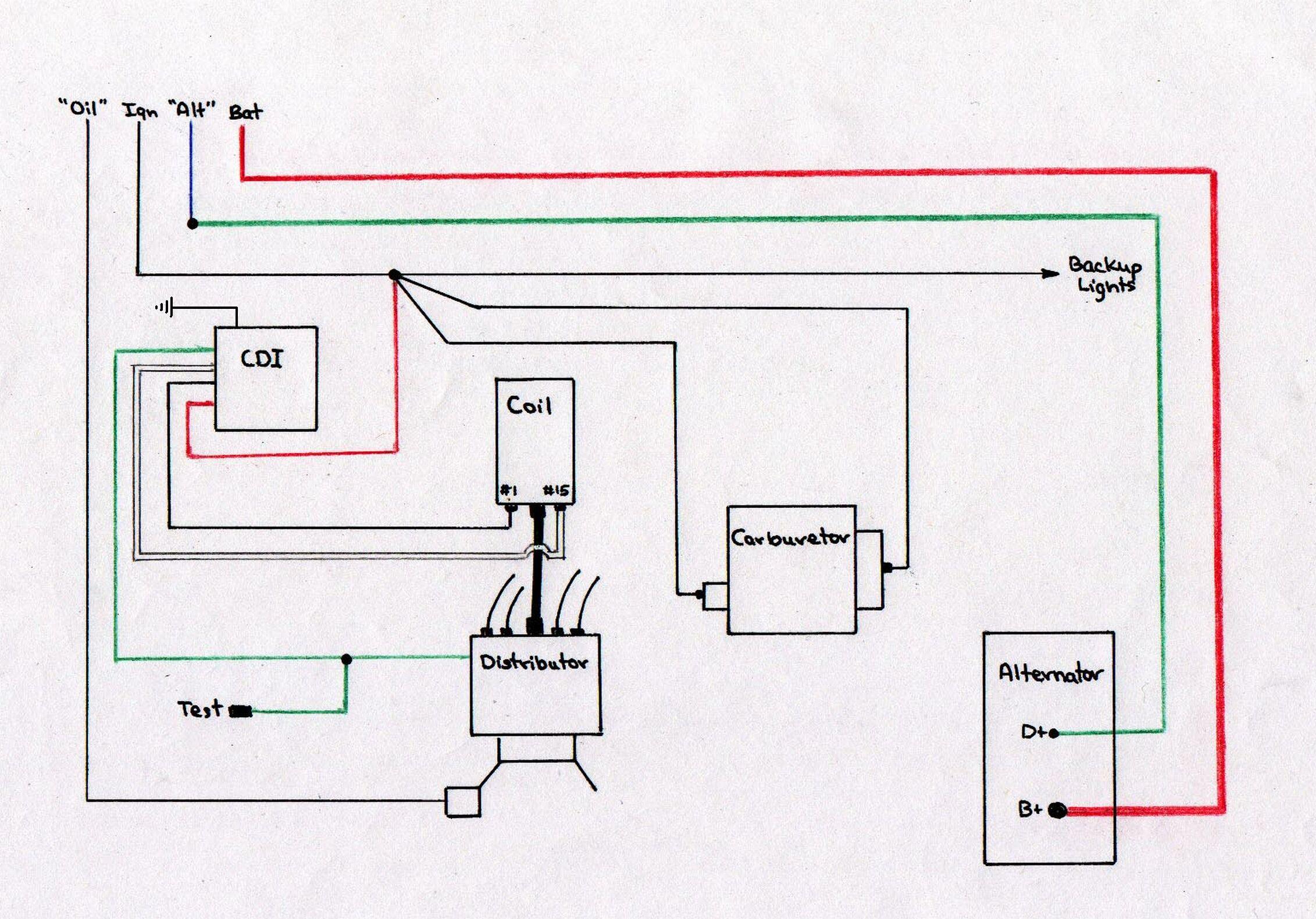 CDI and Alternator Wiringto the warning light in the instrument cluster is blue/green in color. Note: Because of the complexities of the wiring in Dave's engine compartment (equipped with both a Capacitive Discharge Ignition (CDI) system and a CompuFire electronic ignition system), Dave installed what he calls a "power block" onto the left fresh-air nozzle on the fan shroud. There are four positions on this power block -- only three of them are used. From the top - #1, #2, and #3 - power in from the ignition switch on the left side, and power out to the various places it needs to go on the right side. The connections are discussed below and illustrated in the following Power Block Diagram. Power Block Wiring -
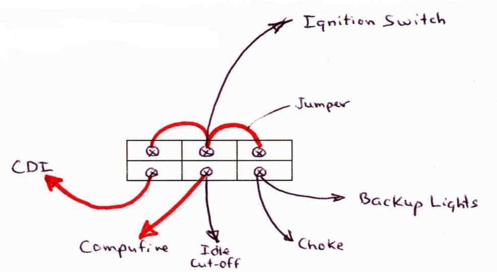 Power Block Diagram
|
|