Compufire Electronic Ignition

"With This Electronic Ignition Module You Will Experience
Quicker Starting, Better Performance and Better Gas Mileage."

Many thanks to CompuFire and Aircooled.Net
for their contributions to this procedure.

~~~

There are two moderm methods to improving your igntion (spark) performance in the VW engine.

  • You can replace your points and condensor with a Points Replacement Unit and continue to use the stock ignition coil. (The stock coil has an internal resistance across the two low voltage terminals of 3-4 ohms, which stops the original points burning up too fast.) The Points Replacement Module results in a very steady spark timing and no need for further point adjusment or replacement. The spark voltage remains the same at roughly 18,000 volts.
  • You can add a CDI - Capacitance Discharge Ignition module. This boosts the spark voltage from about 18,000 to 30+ thousand volts.
  • Note: This procedure describes the installation of a CompuFire Points Replacement system in a SVDA distributor. See Capacitive Discharge Ignition (CDI) for discussion of that system and an installation procedure, including wiring. The wiring interface between the CDI and CompuFire systems is discussed in the following. CDI systems can be triggered by the original points, or (better) a Points Replacement Module. Make sure which version CDI you get matches your chosen method of triggering it.
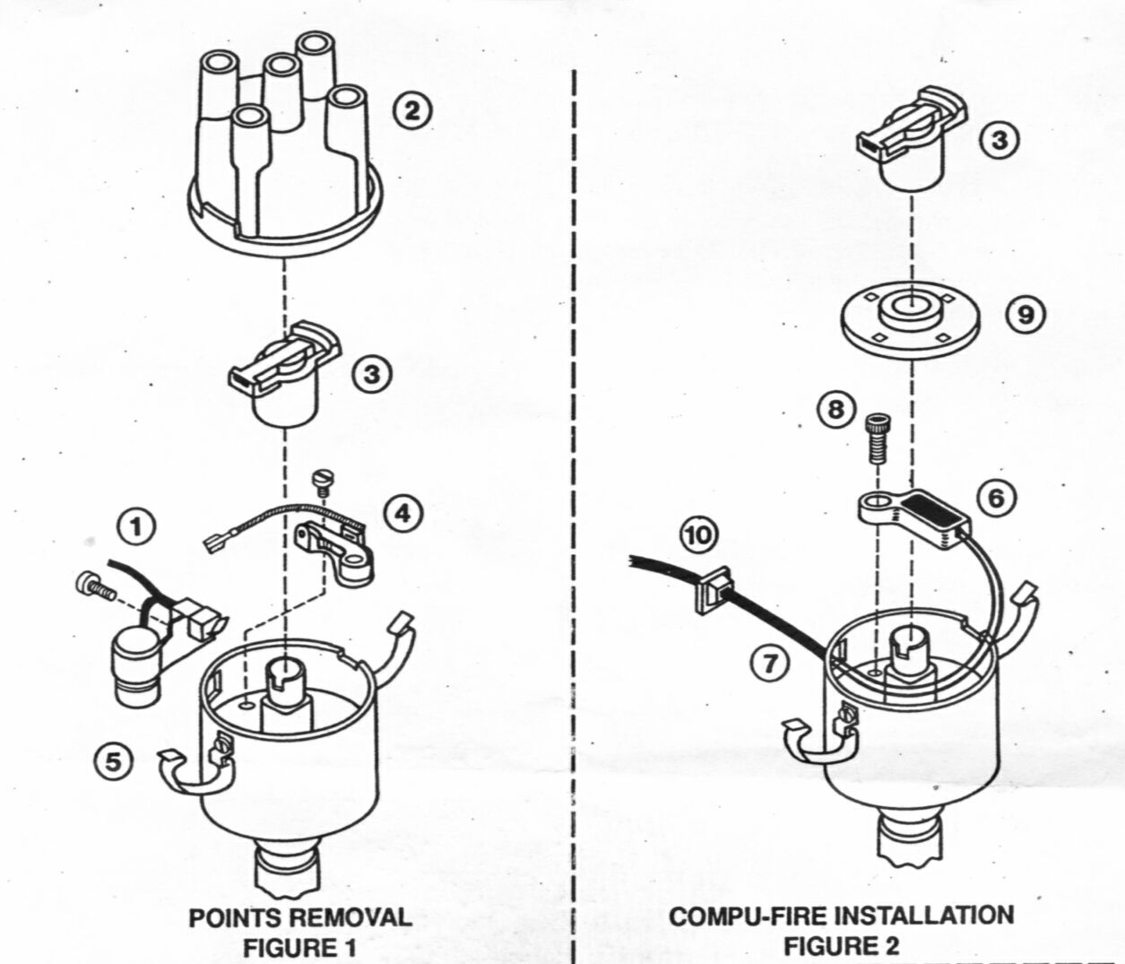
     

    CompuFire Installation

    ~~~

    Procedure (refer to the figure above) -

    Note: For high performance applications you MUST make sure your ignition coil has an internal ballast. If not, the electronic ignition in the distributor will BURN UP and leave you walking. To determine whether your coil is adequate, measure the resistance between terminal #1 and terminal #15 on the coil. The resistance should be on the order of three ohms (when fitting a CDI unit too, a 3-4 ohm coil will work OK, but a low-ohm coil will produce a hotter spark). 3 ohm coils are available that claim to provide triple the output energy of conventional high performance coils - they have more windings in the secondary (high voltage) circuit to boost the output voltage.

    Caution: Before installation of anything to the electrical system, it is recommended that you first disconnect the negative battery terminal to avoid electrical shorts that may damage electrical components on the vehicle.

    SAFETY WARNING: Put the transmission in neutral, set the emergency brake, and block the wheels.

    1. Begin by disconnecting the wire (1) (usually green) from the condenser to the coil (or from the condenser to the CDI unit if you have one).
    2. Note the side of the coil that this wire came off of. This side of the coil is the "negative" and should be marked "-" or "1". The other side is the "positive" "+" or "15".

      Note: If you have a Capacitive Discharge Ignition (CDI) system installed, the black wire from the CompuFire module will be connected to this green wire to the CDI unit.

    3. Remove the distributor cap (2).
    4. Note: It is a good idea to leave the plug wires installed on the cap, to keep them in order.

    5. Rotate the ignition rotor (3) back and forth to insure that the advance mechanism is operating freely.
    6. Remove the ignition rotor (3) and lay it aside for later re-installation. Some rotors havbe a plastic blob in the middle of the brass arm. This has an inbuilt resister under it to help prevent burning at the tip of the rotor. This can stay in place with a Points Replacement Unit but MUST be removed - scraped off and soldered over) or replaced with a full brass arm, if fitting a CDI unit.
    7. Remove the points assembly (4) from the distributor by removing the small flat head screw that secures it.
    8. Note: Make sure you do not lose this screw down inside the distributor! If the screw gets lost in the distributor, it may jam the advance mechanism. Using a screwdriver with a magnetic tip to remove this screw would be ideal. If you do not have a magnetic screwdriver, you can place a magnet on the shank of the screwdriver, such as a refrigerator magnet. The steel bottle/can opener refrigerator magnets usually have a decent magnet on them. Tip: you can magnetise a normal screw driver by wiping one side of a strong magnet repeatedly down the shaft.

    9. With the screw removed from the points, unplug the wire on the points that is going to the condenser (5) and remove the condenser by removing the small screw that holds it on.
    10. Note: Depending on the location of the condenser, you may need to loosen the distributor clamp and rotate or remove the distributor to gain access to the small condenser screw.

      We found it easiest to just remove the distributor. That way you have easy access to the condenser screw and you can install the CompuFire system conveniently on your workbrench. If you do rotate or remove the distributor, put a thin line of white paint on the distributor body running down on the distributor clamp and the engine case. That way you will be able to reinstall the distributor just as it was to maintain the timing.

      Important note: If you've been timing your SVDA or 009 distributor statically, you'll need to invest in a strobe timing light -- once you have the CompuFire system installed you will no longer be able to time the distributor statically, since there are no points.

    11. Now you are ready to install your points replacement module (6). On the bottom side of the pickup unit there is a short "post" -- make sure this "post" fits firmly into the unthreaded hole in the breaker plate that held the points pivot shaft.
    12. A little over an inch away from this unthreaded hole is the threaded hole that was used to secure the points. You do NOT use the old screw that held the points in place - it's not long enough for the module attachement point. Using the 4 x 8 mm socket screw (8) and 3 mm Allen wrench supplied in the hardware pack, secure the module in the same threaded hole that the points screw was installed in. You can save the points, condensoer and original screw in a small baggy for a quick replacement if you are ever unfortunate enough for the Module to fail.
    13. Note: On our SVDA distributor we found a black wire running from the points screw in the braker plate (underside of the points) to the body of the distributor (inside). If you have such a wire, make sure it reattaches under the points replacement module (6) just as it did before.

      Note: There is a slight amount of adjustment in the location of the CompuFire points replacement module (6). Make sure it does not interfere with the high point on the cam lobes. Make sure the screw is tight and does not interfere with the operation of the vacuum advance plate (it will if it's too long).

    14. Feed the two wires (7) from the CompuFire module through the hole that the condensor wire previously went through, then install the plastic grommet (10) onto the wires and slide it up to the body of the distributor.
    15. Note: Make sure you have the right amount of slack in the wires inside the distributor. The wires must not interfere with the operation of the magnetic trigger wheel (9) or vacuum advance mechanism.

    16. When you have the right amount of slack in the wires, push the plastic grommet into the hole in the side of the distributor. The grommet is designed to slightly pinch the wires to keep them from moving.
    17. Note: The square plastic grommet has the flange removed on one side. This side of the grommet must be located on the top side, in the direction of the distributor cap, to avoid interference with the distributor cap when it is installed. If your distributor hole is round, you will have to "round" the square grommet with a razor knife or grinding wheel.

    18. With the CompuFire unit to be used in the SVDA distributor, the kit comes with a small silver ring that is used as a spacer. Slide this ring down onto the distributor shaft; make sure it seats all the way down. It's a tight fit -- you may need to apply some WD40 to a rag and wipe around the shaft to remove accumulated crud and to provide a little lubrication.
    19. Note: It is this ring that properly sets the air gap (about 0.060") between the CompuFire module and the magnetic trigger wheel. The gap must not be outside the range of 0.030” and 0.100”.

    20. Gently press the magnetic trigger wheel (9) down onto the distributor shaft with the raised center section facing up. The wheel should install onto the distributor shaft fairly easily. Note that the wheel is indexed and will go onto the shaft correctly four ways. Rotate it back and forth until you feel it “locate” onto the cam.
    21. Once the trigger wheel is lined up properly, gently press it into place on the spacer ring. It may be stiff the first few times; use the ignition rotor (3) as a tool to fully seat the trigger wheel onto the distributor cam.
    22. Note: If the trigger wheel is not pressed firmly onto the spacer ring, the gap between it and the CompuFire module may be too wide, and the system will not operate properly.

    23. Reinstall the ignition rotor, making sure that the tab in the center seats firmly into the slot of the top of the distributor shaft.
    24. Note: Depending on which ignition rotor you have, you might have to remove some material from the bottom of the rotor so it will seat properly onto the distributor shaft. If not, it will spin freely on the shaft. If you have to remove some material from the ignition rotor, we found the easiest way to get a good flat surface was to carefully use of a bench grinder, taking off just a bit at a time. You can also use a flat file or a Dremel tool. Usually, if an ignition rotor needs to be modified in this way it require the removal of around 1/16-1/8" of material from the bottom of the rotor.

    25. If you removed the distributor, reinstall it now, as follows -
      1. Set the #1 cylinder at TDC.
      2. Note: If you are unsure about cylinder #1 being at TDC, see our Finding TDC Procedure.

      3. Position the distributor to go down into the engine. The hold-down bracket should be over the stud in the crankcase. Before inserting the distributor, check to make sure that the smaller segment of the drive tang on the bottom on the bottom of the distributor is facing the crankshaft pulley. See the following illustration -
      4.  

        Slot in the Distributor Driveshaft

        ~~~

      5. Rotate the rotor so that the tabs at the base of the distributor shaft line up correctly with the slot in the distributor drive and push the distributor firmly into place. The tab and it's matching slot are offset so the distributor shaft can not be placed 180 degrees out in rotation.

        Note: It may be necessary to turn the rotor slightly to mesh the slot in the distributor shaft with the tab at the base of the distributor shaft.

      6. With the distributor properly installed (the tangs match), rotate the distributor body so that the #1 piston line (notch on the distributor rim) is lined up with the rotor.
      7. The notch in the distributor rim that the rotor points to (with # 1 at TDC) should be at ~ 5 o'clock. This will provide timing that is close enough to start the engine.

    26. Replace the distributor cap and secure the clips.

    ~~~

    Wiring Instructions -

    Note: If you have a Capacitive Discharge Ignition (CDI) system in your car, see the second set of wiring instructions below.

    The Points Replacement Module with standard ignition system (no CDI) -

    • The RED wire connects to the positive primary ignition coil terminal. This is the terminal that has the wire from the ignition switch on it.
    • The BLACK wire connects to the minus (-) primary ignition coil terminal. This is the terminal that the points wire was originally connected to.
    • Cut the RED and BLACK wires to length. Strip 1/4" (6 mm) of insulation off the wire, and crimp the fully-insulated female connectors supplied in the kit to the ends of the wires.

      Note: Very Important!! The terminals must be crimped with a proper crimping tool. Poorly crimped terminals will cause erratic ignition performance.

    Wiring both the Points Replacement Module and CDI -

    • The RED wire to the CompuFire unit receives 12 volts from the ignition switch (black wire from the wiring harness). It splices into the thin red wire to the CDI unit; this wire also connects to the ignition switch. The wires to the backup lights, the automatic choke, and the idle cut-off valve also attach to this wire, as they also receive power from the ignition switch. Thus there are SIX wires that must be spliced together -
      • The black wire that runs forward to the ignition switch;
      • The red wire to the CDI unit;
      • The red wire to the CompuFire module;
      • The black wire to the backup lights;
      • The black wire to the automatic choke; and
      • The black wire to the idle cut-off valve.

      We used a large wire nut to connect these six wires. There is probably a more appropriate automotive connection device on the market, which we will look for.

    • The BLACK wire from the CompuFire unit splices into the green wire that goes to the CDI (previously came from the points in the distributor). This black/green wire is the trigger to the CDI (think of it as a points wire).
    • Start the engine and re-set the timing with the strobe light per the Timing Procedure. Note again that you can no longer time the distributor statically. Tighten the distributor clamp.

    Note: If you have a CDI system installed, it is easiest to power the strobe light from the black wire that attaches to the automatic choke, as terminal #15 no longer receives power directly from the ignition switch.

    Note: The CompuFire ignition system is compatible with conventional electronic tachometers. Except for CDI-equipped systems, the tachometer lead remains connected to the minus (-) primary ignition coil terminal (#1). For CDI the green wire from the from the distributor goes to the CDI unit rather than to the #1 terminal on the coil. You will need to splice a wire into this green wire to create a test lead.

    Troubleshooting -

    • No spark from the coil -
      • Using a Volt/Ohm meter (VOM), check to make sure you have 12 volts on coil terminal #15 (the positive (+) terminal) (EXCEPT for CDI-equipped systems) with the ignition switch in the “on” position and with the engine cranking.
      • Note: With the CDI system, a convenient place to measure the incoming voltage is at the automatic choke terminal, connected to the black wire coming from the ignition switch.

      • Check the terminals on the RED and BLACK wires to verify that they are crimped properly and attached to the correct terminals.
      • With the ignition switch off, remove the distributor cap and check the air gap between the CompuFire module and magnetic trigger wheel. The gap should be approximately 0.060” and between 0.030” and 0.100”.

    • If the above steps are okay, check module operation - With the transmission in neutral and the emergency brake set -
      • Set the DC voltmeter on a DC volts range between 15 and 60 volts.
      • Connect the positive meter lead to the minus (-) ignition coil primary terminal (on CDI systems, make this connection to the test lead you have spliced into the green wire from the CompuFire module to the CDI unit).
      • Connect the negative meter lead to engine ground.
      • Crank the engine.
        • If the needle jumps back and forth between approximately 1 volt and 13 volts the ignition system is working properly and the coil is bad or the rotor is bad.
        • If the needle stays at about 13 volts either the RED or BLACK wire is not making connection to the coil primary terminals.
        • If the needle stays at about 1 volt, there is an excessive air gap (greater than 0.125”) between the magnetic trigger wheel and the ignition module, preventing it from switching OR the ignition module has been damaged by connecting the RED and BLACK wires to the wrong terminals on the ignition coil.


    * * * * *


    Design by Erin