|
||

|
|
Steering Column WorkNote: This procedure is a melding of information from several difference sources, including Dave's experience with his '73 Super Beetle. Notes will be added for other years and models as we are aware of them, but they will not be exhaustive, I'm sure. In general, this procedure applies to most any Volkswagen Beetle. Also Note: For purposes of this procedure ONLY, we are going to depart from our normal "front-is-front" convention. It is more understandable, for instance, to discuss the turn signal and wiper switch wiring as being BEHIND the switch assembly rather than "in front" of it. And another: Use of the ignition key is mentioned several times in this procedure. If the ignition key is missing (as sometimes happens when restoring an old Bug), simply remove the door handle and take it to a locksmith to have a new key made. The door handle key and the ignition key are the same -- unless you have replaced the door handles, of course. If you do replace the door handles, you should have the locks changed to match the ignition key. For more information on the ignition key, please see our Ignition Key discussion. We will start this procedure with the steering wheel and work inward, then will work outward back to the steering wheel.
Steering Wheel RemovalNote: This procedure is for the removal and replacement of the steering wheel and hub. Dave installed a Formuling Tradition steering wheel in his car in March 1998. It lasted eight years, until July 2006, when one of the spokes cracked and then broke completely through. Dave tried to repair it with JB Weld and such like, but to no avail. Once again John Connolly at Aircooled.Net came through with a beautiful little Scat steering wheel that was a snap to install. The following instructions for removal and replacement of the steering wheel are fairly generic, hopefully applicable to most situations.
Note: If you are planning to remove the ignition switch later, do not remove the steering wheel yet. Please see the Ignition Switch Replacement procedure later in this article. Note: Do not hammer on the shaft to dislodge the steering wheel.
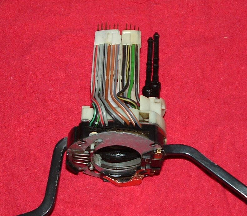
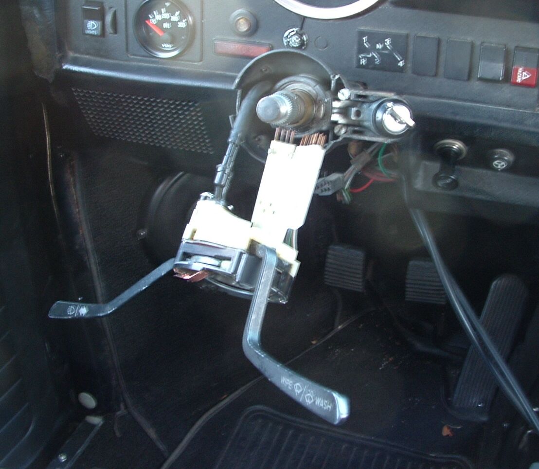
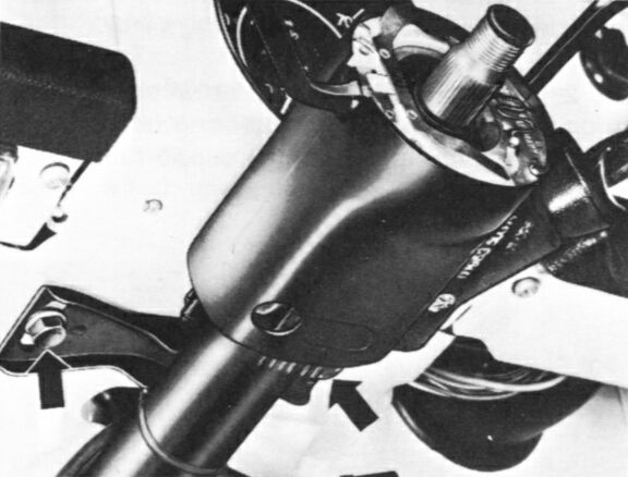
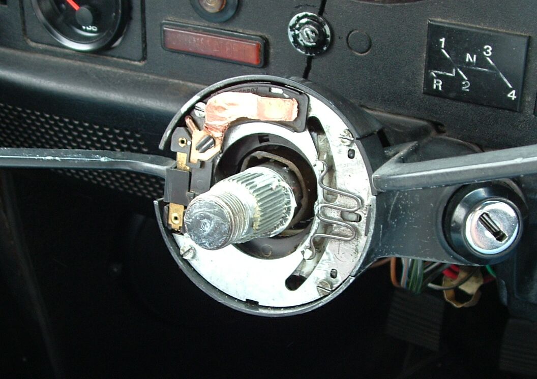 Steering Wheel RemovedTurn Signal/Windshield Wiper Switch Removal
Note: In some models it is necessary at this point to remove the circlip from the groove below the steering wheel splines on the steering column. We did not find this necessary in the Super Beetle.
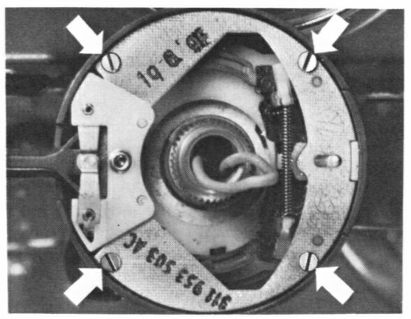 Screws Holding Turn Signal Switch
Note: Bleed the air from the windshield washer reservoir before you remove the water hoses from the valve on the switch. Note: The turn signal and windshield wiper switches must be removed together and then separated after removal. These switches have plastic guide channels behind them that guide the wires into the plugs in the wiring harness. These guide channels will be discussed in more detail below. Caution: Pull the switches out VERY carefully -- the white plastic wiring channels behind the switch assembly are very fragile and easily broken. (See the "Steering Wheel Removed" picture above to view the stripped-down steering column.)
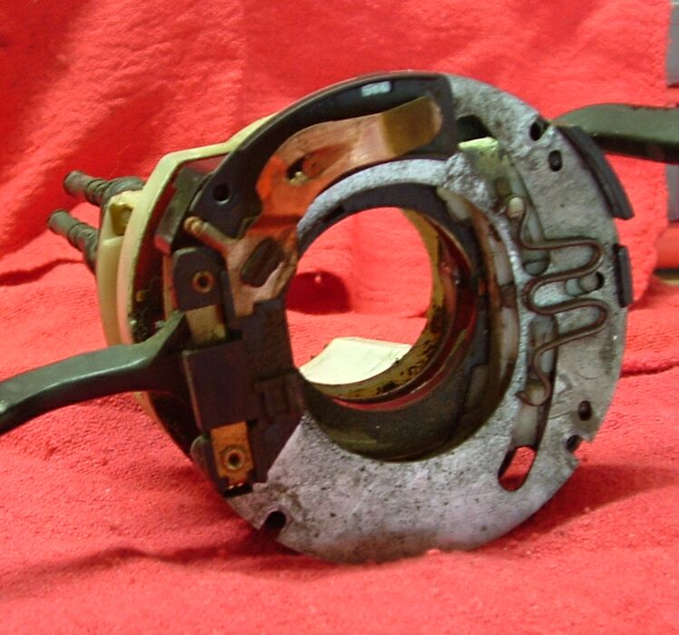 Damaged Horn Contact |
|||||||||||||||||||||||||||||||
Turn Signal Switch Wiring |
Wiper Switch Wiring |
||||||||
| Gry/Red | Gry | Gry/Blk | Brn | Brn/Wht | Brn/Blu | Blk/Gry | Blk/Yel | Grn | Blk |
Note: We found that on the replacement turn signal switch the above wire color convention is not followed. Rather, from left-to-right (as in the above table), the wire colors are Black-Black-Black-Brown-Black-Black. We do not know why the replacement switch does not follow the original wire color convention. John Connolly (Aircooled.Net) speculates that "it's because their position is fixed, and it uses a plug in."
On his page Speedy Jim gives a Ignition Switch Schematic showing the wiring of the ignition switch.
Ignition Switch Removal
Why would you remove the ignition switch? The usual reason for replacing it is because it's been fried! This usually happens when the wire from the ignition switch to the engine compartment shorts to ground. Dave accidently dropped the automatic choke wire onto the alternator with the key on; the result was some nice fireworks and a burned out ignition switch.
To protect the ignition switch, Dave installed a 25-amp in-line fuse in the ignition wire, just after it enters the engine compartment but before it connects to any component (e.g., the coil). (Installation of this fuse was done on the recommendation of John Connolly at Aircooled.Net.)
regarding things that can happen to the ignition switch.
Note: The following assumes that you have removed the turn signal and windshield washer switches per the foregoing.
- Again, assure that the battery ground strap has been removed.
- Make sure the ignition/steering lock is freed and the the key is in the first positon to the right (the "on" position, not the "start" position).
- Remove the two screws that hold the steering/ignition lock retainer plate and remove the plate itself.
- Having removed the two screws that hold the steering/ignition lock retainer plate, the ignition assembly can be removed from the steering column housing.
- On 1973 and later cars, unplug the ignition switch from the wiring harness if you have not already done so. On earlier cars, push the wires through while you withdraw the steering ignition lock far enough to work on it.
Note: There is a spring behind the retainer plate. Make sure to note the orientation of the spring; lay it aside in a safe place.
1968 thru 1971 Models -
- Insert the key into the lock cylinder and turn the key slightly, then pull the cylinder out until the retaining spring on the top or side is visible in the opening.
- Using a nail or a piece of steel wire inserted through the hole in the lock assemblys housing, depress the retaining spring on the lock cylinder while pulling the lock cylinder out.
- Remove the lock cylinder by turning the key all the way to the 'start' position and pulling the lock cylinder out of the housing.
1972 thru 1976 Models -
Note: Beginning with the 1972 models, the new type ignition switch has a plug on the wiring harness (as noted above) that makes it possible to remove and install the lock cylinder and the ignition switch without having to remove the steering lock first. The turn signal and wiper switches must, however, be removed first.
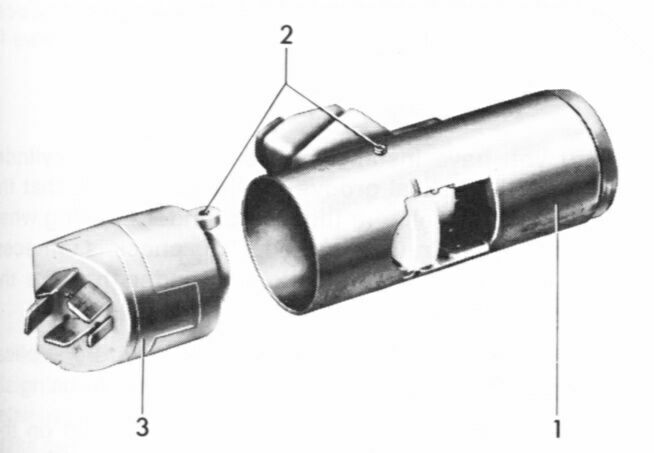
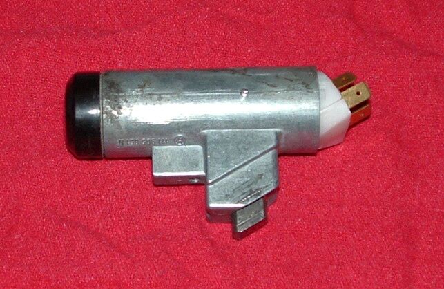
Typical Late-Type Ignition Switch
2- Setscrew Holes
3- Ignition Switch
- Remove the lock cylinder by turning the key all the way to the "start" position and pulling the lock cylinder out of the housing.
- Note the small hole in the side of the lock assembly. The hole may have a very small screw in it (our 1973 SB does). Unscrew the screw (if present) and press a nail or stiff wire into the hole while pulling on the ignition switch at the end of the lock assembly.
Note: Don't lose the tiny screw! You will need it when replacing the ignition switch.
1976 and Later Models -
- Inspect the lock assembly's housing. If there is no hole at the point indicated in the following picture, carefully drill a hole that will allow you to insert a nail or a piece of steel wire.
Caution: Remove the turn signal and windshield wiper switches before you attempt to drill the hole. The sealing plate should not be removed, as doing this may break off the lug on the turn signal switch.
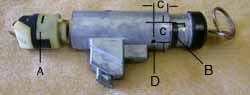
Late-Type Ignition Assembly
"A" - Ignition Switch (electrical part). "B" - Retaining spring on the lock cylinder. "C" - 11mm dimension where hole must be
drilled."D" - Hole through which stiff wire must be
inserted to depress retaining spring.~~~ - Using a nail or a piece of steel wire inserted through the opening, depress the retaining spring on the lock cylinder.
- Remove the lock cylinder by turning the key all the way to the "start" position and pulling the lock cylinder out of the housing. A strong, steady pull will do the job.
~~~ Ignition Switch Reinstallation
Older Models -
- Older models has a helical groove in the locking mechanism for the pin. With the pin depressed slightly, you should be able to move the steering column locks slide to the right until the slide pin is flush with the housing.
- The earlier-type lock cylinder (without the black plastic cap on the end) must be installed with the key inserted in the lock cylinder. Then use the key to turn the cylinder to the left stop position to make sure it is working, then remove the key.
Note: The cylinders with black caps have been used as replacement parts in earlier cars since 1972.
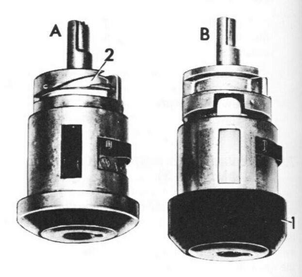
Lock Cylinders for Cars With Locking Steering Columns
Newer version (B) has black plastic cap (1). Early version (A) has helical groove for pin. ~~~ Newer Models (Black Cap) -
- Reconnect the electrical portion of the ignition switch onto the end of the lock/ignition assembly, making sure that the hole in the side of the switch lines up with the hole in the lock cylinder body.
- Reinstall the small screw in the side of the lock cylinder body.
- Make sure that the switch is in its locked position before you attempt to install the lock cylinder -- key turned all the way to the left; then remove the key.
- Push the lock cylinder into the housing in the steering column, without using the key.
- Insert the key and turn it all the way to the left to check the locking operation.
- Do not reconnect the harness plug onto the end of the ignition switch yet, as it will be in the way of the turn signal and wiper plugs. You will reconnect all three at the same time.
Caution: Do not attempt to install the late-type cylinder with the key installed; otherwise the lock may be damaged.
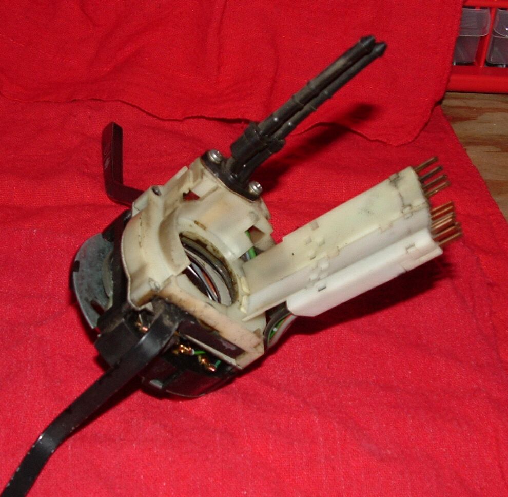
Lock Assembly Out of Dave's '73 SB
~~~ ~~~ Turn Signal/Windshield Wiper Switch Reinstallation
Reassembly of the other steering column internals is essentially the reverse of the removal.
- Replace the steering/ignition lock retainer plate (two screws), making sure to properly install the spring behind
it.
Note: Where the spring goes is obvious -- there is a hole in the steering column body just to the left of the key switch in which the spring resides.
Turn Signal/Wiper Switch Assembly
Ready for Reinstallation~~~ 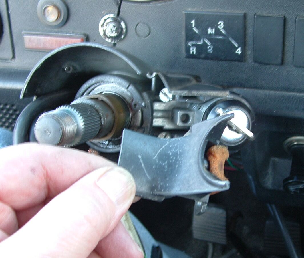
Ignition Lock Retainer Plate
Showing Spring Location~~~ - Thoroughly inspect the switches for wear and/or damage if you haven't already, and make any necessary repairs (e.g., to the horn ring contact and the plastic wiring channels).
- Assemble the turn signal and windshield wiper switches together, making sure that the four little tubes at the corners pass through both switch assemblies and are flush on both sides.
- Make sure the switch wiring is properly installed in the plastic guide assemblies (see the table above).
- Make sure the wiring guide channels are properly connected to the switch assembly and to each other (note the tabs at the connection points), and make sure the small pieces at the end of each channel are in place (these hold the wiring tips in the correct orientation so they will mate with the plugs on the wiring harness properly).
- Inspect the openings in the steering column housing through which the washer nozzles and wiring guide assemblies will pass (you will need a good flashlight). Clean these openings thoroughly with a long Q-tip dampened with mineral spirits. Allow the solvent to evaporate away before installing the wiring guide assemblies.
- Pull the two windshield washer hoses through the steering column body as far as you can, then reattach them to the washer nozzles on the switch. Route the inlet hose (lower nozzle) through the firewall into the luggage compartment and on to the washer reservoir. Route the outlet hose (upper nozzle) through the firewall into the fresh air box, then reattach it to the washer sprayer.
- Carefully reinstall the turn signal/wiper switches back into the steering column housing, making sure that the wiring assemblies properly pass through the opening that is provided for them.
- Secure the switch assembly in the steering column housing with the four long screws that you removed previously.
- If applicable, replace the circlip from the groove below the steering wheel splines on the steering column.
- Reattach the three electrical plugs to the three switches at the rear of the steering column switch housing.
- Turn the steering wheel hub upside down and examine the horn contact ring. Wear will be evident, but if the ring is damaged it must be replaced.
- Place the turn signal lever in its central position.
- Replace the steering wheel as follows.
Note: The opening for the wiring assemblies is the same shape (in cross section) at the wiring assemblies. Make sure to properly guide the wiring assemblies through this opening, otherwise you will have trouble installing the switch assembly in the steering column housing and may damage the wiring tips.
Note: During turn signal switch installation, be sure that the contact ring between the ball bearing and the steering column is positioned properly and that the turn signal switch lever is in its central position. Otherwise, the canceling cam will be damaged by the tongue of the contact ring when the steering wheel is installed.
~~~ Steering Wheel Reinstallation
- Set the steering wheel and hub upside down on the workbench.
- You will find one or two small holes in the bottom of the hub, toward the edge. This (these) hole(s) are for the directional signal cancelling pin(s).
- Carefully tap the directional signal cancellation pin(s) provided with the steering wheel kit into the hole(s) provided in the base of the steering wheel hub. Make sure the pin(s) is (are) seated firmly and that they protrude 7/16" (11 mm).
Note: Better quality steering wheels (e.g., Scat) have two directional signal canceling pins. Please once again see the picture of the steering column with the steering wheel removed -
Steering Wheel Removed
~~~ On the right side of the column, note the sideways "M" device. This is the directional signal cancelling mechanism. If you have just a single return pin, it must fit into the center portion of the "M"; if you have two return pins, they must fit into the two outer portions of the "M". The two-pin system gives a much more positive return.
Note: If the cancellation pin(s) is (are) missing or loose, the turn signals will not return to the "off" position as they should. We made a new pin out of an appropriately-sized nail and secured it in place with epoxy.
- Before installing the new steering wheel, confirm that the wheels are pointed straight ahead centered, and the turn signal switch is in its central position.
- Apply a thin coat of lithium grease to the splines on the steering wheel shaft.
- Make sure the directional signal cancellation pin(s) is (are) aligned properly in the "M" (as described above), then carefully slide the steering wheel hub onto the shaft.
- Adjust the clearance between the steering column switch housing and the steering wheel hub. This distance must be 2 to 3 mm. To adjust the distance, loosen the two screws that secure the switch to the car body or steering column tube, then move the switch housing in the slotted holes. (See the pictures below.)
- Replace the steering column spring washer and nut. Torque the nut to no more than 35 ft-lbs.
- Connect the horn wire to the central cap and press the cap into the center of the steering wheel.
- Reconnect the negative battery cable.
Note: Make sure that the steering wheel is oriented properly for the straight ahead position (e.g., for a three-spoke steering wheel, the center spoke is point straight down).
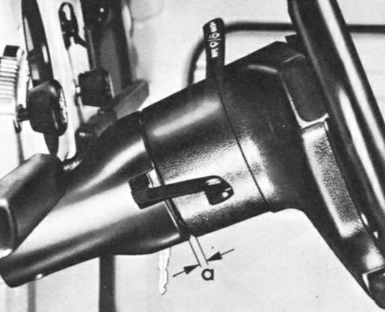
Gap Between the Wheel and Switch.
Column Tube Mounting Bolts.
~~~ Note: This adjustment is very important, but quite difficult to do. If this adjustment is incorrect, the switches in the steering column will not work properly. In my Super Beetle the "two screws that secure the switch" are the column tube mounting bolts -- 6mm hex. They are nestled nicely behind a mess of wiring and switch connections underneath the dashboard. These bolts are indeed in slotted holes, and once they are loosened the whole switch assembly can be moved a bit. I found it easiest to do with the steering wheel removed, tapping around the switch tube with a rubber hammer. It is very difficult to do with the steering wheel in place.
Note: Once you have the steering wheel and hub installed back on the steering column, you may find that the horn does not work. If this is the case, you will have to pull the steering wheel back off of the column and bend the copper contact (see the picture above) so that it will contact the horn ring at the base of the steering wheel hub.
When operational, the copper contact on the turn switch is in constant contact with the horn ring -- it is always "hot." You activate the horn by pressing the center button on the steering wheel, thus providing ground, completing the circuit, and sounding the characteristic VW "hoot."
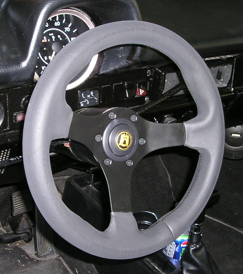
Scat Steering Wheel
(Provided by Aircooled.Net)
* * * * *
Note: On 1970 and 1971 models it is not necessary to turn the key unless a later-type lock cylinder has been installed. The later type is easily identifiable as it has a black plastic cap on the key end.
Also Note: The lock cylinder may not want to come out easily. We found that a steady, strong pull finally did the job.